

What You’ll Learn 🎥
Configure the Video Acquisition module in DewesoftX to sync video with analog, digital, counter, CAN, XCP, and other signals
Select and set up cameras—DirectX webcams, GigE (DS‑CAM family), high-speed Photron FASTCAM, and Optris thermal cameras
Choose optimal frame rates, storage modes (constant, fast-on-trigger, slow-then-fast), and trigger settings for precise synchronized acquisition
Calibrate for timing accuracy: understand delays and jitter in webcams versus hardware-synced DS‑CAM and Photron systems
Perform post-acquisition video synchronization with DewesoftX’s analysis tools—align *.avi files to data channels for replay and review
Integrate video frames with data plots, cursors, and markers for enhanced event analysis—e.g., fuse switching or mechanical operations
Capture dynamic events up to millions of FPS using Photron FASTCAMs, including setup of triggers, pre-trigger buffer, and playback synchronization
Export synchronized recordings and create annotated reports combining video and measurement data
Course overview
The Video Acquisition course empowers engineers and test professionals to leverage video alongside signal data for synchronized measurement analysis in DewesoftX. You’ll begin with configuring the Video module—connecting various cameras (webcams, GigE DS‑CAMs, Photron, and infrared), setting frame rates, storage options, and triggers to precisely align video with analog and digital channels.
Next, the course explains synchronization challenges: webcams provide time-stamped frames with inherent latency and jitter, which can be compensated by entering delay values; however, for high-accuracy applications, hardware-triggered cameras like DS‑CAM and Photron are recommended. Through detailed walkthroughs, you’ll learn to configure Photron FASTCAMs using Dewesoft counter inputs, Ethernet configurations, pre-trigger settings, and analyze performance up to millions of frames per second.
In the analysis phase, you’ll master post-processing in DewesoftX: copying video files next to measurement data, initiating manual or automatic sync, and reviewing frames in sync with signal cursors—ideal for pinpointing events like switch-offs or mechanical actions. Finally, you’ll learn how to export combined video-data files and build comprehensive, annotated reports for sharing actionable insights with your team or clients.
Video acquisition in DewesoftX
The DewesoftX video acquisition module offers the ability to acquire video signals alongside other data sources. A wide range of cameras is supported:
Low-speed cameras (up to 30 FPS): any DirectX compatible camera
Medium speed cameras (up to 600 FPS VGA resolution): Dewesoft DS-CAM cameras
High-speed cameras (up to 20.000 FPS at VGA resolution): where we combine data and video in post-processing or directly use the Photron driver inside Dewesoft X (please consult the user's manual for details)
Thermovision cameras: Optris thermovision cameras
| Required hardware | Sirius, Dewe-43, Webcam, DS-CAM |
| Required software | Prof (for DS-CAM support) |
| Setup sample rate | At least 1 kHz |
Dewesoft cameras
For applications requiring video that is truly synchronized with the dynamic sample rate, DS-CAM cameras are supported. These cameras provide high-quality images with automatic shutter speed (which is selectable) and are controlled directly by the A/D card, which generates a pulse to trigger the camera. The result is a highly accurate correlation between each frame and the acquired data.
Thermal cameras from Optris and ultra-high-speed cameras from Photron are also supported. Photron cameras can acquire more than 2 million frames per second, although at limited resolution.
DS-CAM-88c, DS-CAM-120c (gigabit-ethernet camera)


All DS-CAM cameras are designed to be highly resistant to shock and vibration.
resolution
640x480 at 88 fps
320x240 at 167 fps
160x120 at 289 fps
auto-shutter
auto-gain
auto white-balance
color
DS-CAM-175c, DS-CAM-320c (gigabit-ethernet camera)
Specifications:
power-over-ethernet option
the best performance with SIRIUS S-BOX
IP67 version available
auto-shutter
auto-gain
auto white-balance
color
DS-CAM-175chas the following specifications:
1456x1088 at 68 fps
640x480 (VGA) at 178 fps
DS-CAM-320chas the following specifications:
728x544 at 266 fps
640x480 (VGA) at 328 fps
DS-CAM-600m, DS-CAM-600c, DS-CAM-600cw (gigabit-ethernet camera)


Specifications:
full HD resolution (1920x1080)
real-time onboard JPEG compression
power-over-ethernet option
the best performance with SIRIUS S-BOX
IP67 version available
color and monochrome
DS-CAM-600bw/chas the following specifications:
1920x1080 (HD) at 300 fps
640x480 (VGA) at 600 fps
Applications
All DS-CAM cameras are designed to be highly resistant to shock and vibration.
These cameras support both triggered (synchronized) and free-run modes. Video is captured using real-time data streaming, even at full resolution, which requires a Gigabit Ethernet (GigE) port.
The system requirements for GigE cameras are:
Gigabit Ethernet LAN port
Dewesoft X
(Clock possibility)
Core2Duo CPU
The applications at which the cameras are used:
machine diagnostic
product quality check
non-destructive testing
research and development
automotive crash testing
impact tests
logistics and transportation
manufacturing
Specifications
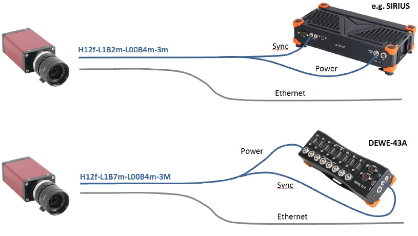
If you have multiple DS-CAM cameras, we can provide adapters for syncing, powering, and connecting multiple cameras to Dewesoft instruments.
CAM-BOX
Adapter box (single camera): For connecting one DS-CAM-88/120 to a Dewesoft instrument. Combines sync and power into a single camera connector.
CAM-BOX1
Adapter box (up to 4 cameras): For connecting up to four DS-CAM-88/120 units. Combines sync and power into the camera connectors. Requires an external GigE switch.


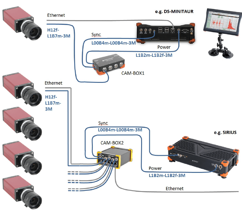
CAM-BOX2
Distribution box (DS-CAM-88/120): Connects up to four cameras with a wide-range power input (9–36 VDC) and an integrated GigE switch.


CAM-BOX3
Distribution box (DS-CAM-600): Connects up to four DS-CAM-600 units with a wide-range power supply input (9–36 VDC), an integrated GigE switch with 4x PoE, and a SIRIUS chassis with a 1.5U height.


3rd party camera support
If your application requires video, you are not limited to using Dewesoft's DS-CAM cameras.
DewesoftX software supports all compatible DirectX cameras, as well as third-party Optris thermal cameras and Photron ultra-high-speed cameras. All video sources are fully synchronized with analog data acquisition.


DS-CAM-88c, DS-CAM-120c
The DS-CAM-88c and DS-CAM-120c are high-speed Gigabit Ethernet cameras with the following key specifications:
DS-CAM-120c: 120 fps @ VGA (640x480)
DS-CAM-88c: 88 fps @ VGA (640x480)
Color
Auto-gain
Auto-shutter (also fixed shutter possible)
Auto-white balance
Triggered and free-run mode
Standard C-Mount
Small compact form factor
Low power consumption
Ruggedized (high-shock and vibration resistant, aluminum housing)
Real-time data streaming with full resolution
These cameras support the high-performance industrial standard GigE Vision. Introduced in 2006, this standard provides a framework for transmitting high-speed video and related control data over Ethernet networks.
The benefits are high-speed data transfer rates up to 1GBit/s (based on 1000Base-T) connectable to every standard GigE Ethernet port and cable lengths up to 100m.
Dewesoft utilizes the OptoStream SDK for GigE communication with cameras that support the GigE Vision standard.
System requirements:
1 Gigabit-Ethernet port
Good PC performance (Core i5 CPU or better recommended, 4 GB RAM)
DewesoftX
The latest OptoMotive OptoStreamSDK
The latest Dewesoft GigE driver (cdv)
Technical specifications
Optical
| DS-CAM-88c | DS-CAM-120c | |
|---|---|---|
| Image sensor | Sony IT ICX414AL/AQ with HAD microlens, progressive scan | Sony IT ICX618AL/AQ with Exview HAD CCD II microlens |
| Sensor type | CCD | CCD |
| Optical size | 1/2 " | 1/4 " |
| Effective chip size | 6.5 x 4.9 mm | 4.46 x 3.80 mm |
| Cell size | 9.9 x 9.9 um | 5.6 x 5.6 um |
| Picture size (max) | 656 x 492 pixel | 646 x 492 pixel |
| ADC | 14 bit | 14 bit |
| Gain control | 0 - 35 dB; auto-gain | 0 - 32 dB; auto-gain |
| Exposure time | 26 us - 60 s; auto-shutter | 58 us - 60 s; auto-shutter |
| Smart functions | auto-white balance, color correction, edge filter (sharpness), hue, sat. | auto-white balance, color correction, edge filter (sharpness), hue, sat. |
| Max, frame rate (at full resolution) | 88 fps | 120 fps |
Power
| DS-CAM-88c | DS-CAM-120c | |
|---|---|---|
| Supply voltage | 8 to 30 VDC | 8 to 30 VDC |
| Power consumption | <3,6 W (@ 12 VDC) | <3,7 W (@ 12 VDC) |
| Power-over-ethernet | optional | optional |
Trigger input
| Voltage level representing logical 0 | 0.0 ... 1.0 V DC |
| Undefined state between 0 and 1 | 1.0 ... 3.0 V DC |
| Voltage level representing logical 1 | 3.0 ... 24.0 V DC |
| Absolute maximum voltage (above → damage!) | 36 V (only with an external resistor of 3.3 kOhm in series) |
Trigger input
| Maximum current source for output | 20 mA, open emitter |
Mechanical
| External housing (h x w x l) | 86.4 x 44.0 x 29.0 [mm] |
| Housing | aluminum case |
| Weight | < 200 g (without lens) |
| Storage temperature | -10 °C .. +70 °C (14 °F .. +158 °F) |
| Operating temperature | 5 °C .. +45 °C (+41 °F .. +113 °F) |
| Operating humidity | 25% .. 80% (no condensation) |
| Storage humidity | 25% .. 95% (no condensation) |
| Lens mount | C-mount (CS-mount optional) |
| Connectors | Screw mount Ethernet RJ45; EIAJ (Hirose) 12 pin (matching part: HiroseHR10A-10P-12S(73)) |
| Conformity | CE, FCC Class B, RoHS, GigE Vision, GenICam |
Connections
On the rear side of the camera, there are two connectors: a 12-pin HIROSE connector (matching part: Hirose HR10A-10P-12S(73))—used for power, trigger, and other digital signals. An Ethernet connector, which follows the GigE Vision standard pinout.


Power/trigger connector pinout
12pin Hirose connector (matching part: Hirose HR10A-10P-12S(73)) on camera rear side


| PIN # | SIGNAL |
|---|---|
| 1 | GND (for Power and RS232) |
| 2 | Power (+8...+30 V DC) |
| 3 | - |
| 4 | Camera In 1 (TRIGGER) |
| 5 | - |
| 6 | Camera Out 1 (open emiter, max. 20 mA) |
| 7 | Camera In GND |
| 8 | RxD (RS232) |
| 9 | TxD (RS232) |
| 10 | Camera Out Power (for digital outputs) |
| 11 | Camera In 2 |
| 12 | Camera Out 2 |
SIRIUS connection example
Image 11 shows a typical SIRIUS measurement system, consisting of one SBOX (integrated PC) on the bottom and one SIRIUS slice on top (rear view).
The camera is connected directly to the Gigabit LAN port. A second cable supplies power (from the SBOX Power Out port) and trigger signals, which are connected to the SYNC port of the SIRIUS slice. This configuration ensures that the camera frames are perfectly synchronized with the analog data acquired by Dewesoft.


Connecting multiple cameras
If you need to connect multiple cameras, a dedicated unit called CAM-BOX2 is available. It enables connection and synchronization of up to four cameras.
wide-range voltage input (9-36V)
an industrial Gigabit-Ethernet-Switch (without Power-over-Ethernet! No supply for DS-CAM-600!)
Power and Sync distribution for up to 4 cameras.
Small dimensions: 115 x 62 mm (front) and 135 mm deep


Camerabox connector (mating cable connector: FGG.1B.307CLAD52)


Power supply (mating cable connector: FGJ.1B.302CLLD42Z)


Sync connector (mating cable connector: FGG.00.304CLAD27Z)


Connections overview


Benchmarks
The following tests were performed using a SIRIUS SBOX and 1 to 4 DS-CAM cameras connected via the CAM-BOX2. Setup details are as follows:
1 to 4 cameras connected over CAM-BOX2
SBOX: 128GB SSD -> max 190 Mbyte/s write rate
CPU: Intel Core i7 QM57; 2.0GHz; 4GB RAM
camera(s) clocked by SIRIUS
Dewesoft X
OptoMotive OptoStreamSDK
GigE Camera driver (Plugin)
storing data to file, video buffer stable around 0.1%
with checked "optimize for switched network"
Achieved frame rates (fps)
| Number of Cameras | X res | Y res | DS-CAM 88c | DS-CAM-120c |
|---|---|---|---|---|
| 1 | 640 | 480 | 88 | 120 |
| 320 | 240 | 165 | 195 | |
| 320 | 120 | 280 | 300 | |
| 2 | 640 | 480 | 88 | 120 |
| 320 | 240 | 165 | 195 | |
| 320 | 120 | 280 | 210 | |
| 3 | 640 | 480 | 88 | 90 |
| 320 | 240 | 165 | 195 | |
| 320 | 120 | 280 | 210 | |
| 4 | 640 | 480 | 88 | 60 |
| 320 | 240 | 165 | 195 | |
| 320 | 120 | 280 | 210 |
DS-CAM-175c, DS-CAM-320c
The DS-CAM-175c and DS-CAM-320c are high-speed Gigabit Ethernet cameras with the following key specifications:
DS-CAM-175c: 178 fps @ VGA (640x480)
DS-CAM-320c: 328 fps @ VGA (640x480)
Color
Auto-gain
Auto-shutter (also fixed shutter possible)
Auto-white balance
Triggered and free-run mode
Standard C-Mount
Small compact form factor
Low power consumption
Ruggedized (high-shock and vibration resistant, aluminum housing)
Real-time data streaming with full resolution
These cameras support the high-performance industrial standard GigE Vision, introduced in 2006. This standard provides a robust framework for transmitting high-speed video and control data over Ethernet networks.
The benefits are high-speed data transfer rates up to 1GBit/s (based on 1000Base-T) connectable to every standard GigE Ethernet port and cable lengths up to 100m.
Dewesoft uses the OptoStream GigE SDK to communicate with cameras that support the GigE Vision standard.
System requirements:
1 Gigabit-Ethernet port
Good PC performance (Core i5 CPU or better recommended, 4 GB RAM)
Dewesoft X
The latest OptoMotive OptoStreamSDK
The latest Dewesoft GigE driver (cdv)
Technical specifications
Optical
| DS-CAM-175c | DS-CAM-320c | |
|---|---|---|
| Image sensor | Sony IMX273 | Sony IMX287 |
| Sensor Type | CMOS | CMOS |
| Max resolution | 1456x1088 | 728x544 |
| Optical size | 1/2.9'' (6.3 mm diagonal) | 1/2.9'' (6.3 mm diagonal) |
| Pixel size | 3.45 x 3.45 um | 3.45 x 3.45 um |
| FPS | 68 FPS @ 1456x1088116 FPS @ 1280x720145 FPS @ 800x600178 FPS @640x480 | 266 FPS @ 728x544328 FPS @640x480 |
| Dynamic range | 71.6 dB autogain function | 74.4 dB autogain function |
| Shutter | Global | Global |
| Shutter time | Auto shutter function | Auto shutter function |
| Color correction | Auto white balance | Auto white balance |
| Max, frame rate (at full resolution) | 175 fps | 320 fps |
Power
| DS-CAM-175c | DS-CAM-320c | |
|---|---|---|
| Supply voltage | 8 to 30 VDC or 802.3af PoE | 8 to 30 VDC or 802.3af PoE |
| Power consumption | 2,79 W @ 12 VDC; 3,26 W PoE | 2,77 W @ 12 VDC; 3,23W PoE |
Trigger input
| Voltage level representing logical 0 | 0.0 ... 1.0 V DC |
| Undefined state between 0 and 1 | 1.0 ... 3.0 V DC |
| Voltage level representing logical 1 | 3.0 ... 24.0 V DC |
| Absolute maximum voltage (above → damage!) | 36 V (only with an external resistor of 3.3 kOhm in series) |
Mechanical
| External housing (h x w x l) | 86.4 x 44.0 x 29.0 [mm] |
| Housing | aluminum case |
| Weight | < 200 g (without lens) |
| Operating temperature | 5 °C .. +45 °C (+41 °F .. +113 °F) |
| Operating humidity | 20% .. 80% (no condensation) |
| Lens mount | C-mount |
| Connectors | Screw mount RJ45 Ethernet connector, Hirose HR10-10R-12PA(73) |
Connections
On the rear side of the camera, there are two connectors: a 12-pin HIROSE connector (matching part: Hirose HR10A-10P-12S(73)) — used for power, trigger, and other digital I/O. An Ethernet connector, following the standard GigE Vision pinout.
Power/trigger connector pinout
12-pin Hirose connector (Hirose HR10A-10P-12S(73)) located on the rear of the camera.
| PIN # | SIGNAL |
|---|---|
| 1 | GND (for Power and RS232) |
| 2 | Power (+8...+30 V DC) |
| 3 | - |
| 4 | Camera In 1 (TRIGGER) |
| 5 | - |
| 6 | Camera Out 1 (open emitter, max. 20 mA) |
| 7 | Camera In GND |
| 8 | RxD (RS232) |
| 9 | TxD (RS232) |
| 10 | Camera Out Power (for digital outputs) |
| 11 | Camera In 2 |
| 12 | Camera Out 2 |
SIRIUS connection example
In the image, you can see a typical SIRIUS measurement system, consisting of: One SBOX unit (an integrated PC) on the bottom one SIRIUS slice on top (rear view shown)
The camera is connected directly to the Gigabit LAN port. A second cable provides power (from the SBOX Power Out port) and connects the trigger line to the SYNC port of the SIRIUS slice. This ensures the camera frames are perfectly synchronized with the analog data acquired by Dewesoft.
Connecting multiple cameras
If you need to connect more than one camera, a dedicated unit called CAM-BOX2 is available, which includes:
wide-range voltage input (9-36V)
an industrial Gigabit-Ethernet-Switch (without Power-over-Ethernet! No supply for DS-CAM-600!)
Power and Sync distribution for up to 4 cameras.
Small dimensions: 115 x 62 mm (front) and 135 mm deep
Camerabox connector (mating cable connector: FGG.1B.307CLAD52)
Power supply (mating cable connector: FGJ.1B.302CLLD42Z)
Sync connector (mating cable connector: FGG.00.304CLAD27Z)
DS-CAM-600
The DS-CAM-600 is a high-speed Gigabit Ethernet camera with the following key specifications:
600fps @ VGA (640x480)
Full HD resolution 1920x1080
Real-time data streaming with full resolution
Monochrome
Power-over-Ethernet (PoE)
Real-time JPEG compression
Sync (Triggered and free-run mode)
Adjustable shutter time
Standard C-Mount
Small compact form factor
Ruggedized (high-shock and vibration resistant, aluminum housing)
The camera supports the high-performance industrial standard GigE Vision, introduced in 2006. This standard provides a framework for transmitting high-speed video and related control signals over Ethernet networks.
The benefits are: high-speed data transfer rates up to 1GBit/s (based on 1000Base-T) connectible to every standard GigE Ethernet port and cable lengths up to 100m.
Dewesoft uses the OptoMotive GigE SDK for communication with cameras that support the GigE Vision standard.
System requirements
1 Gigabit-Ethernet port
Good PC performance (Core i5 CPU or better recommended, 4 GB RAM)
DewesoftX
OptoMotive GigE Vision SDK
Dewesoft GigE driver (cdv) 2.0
Technical specifications
Power
| Supply voltage | Power-over-Ethernet (42-57V) |
| Power consumption | 6 W |
Digital I/O
| Recommended input voltage | 0 to 3,3 VDC |
| Voltage level representing logical 0 | 0 to +0,8 VDC |
| Undefined state between 0 and 1 | > +0,8 VDC to +2,0 VDC |
| Voltage level representing logical 1 | > +2,0 VDC to 3,3 VDC |
| Absolute maximum voltage (above → damage!) | +/- 24 VDC |
Optical
| Image sensor | CMOSIS CMV2000 2E5M1PP |
| Sensor type | CMOS |
| Sensor resolution (H x W) | 2048 x 1088 |
| Optical size | Diagonal 12.7 mm (2/3") |
| Pixel size (in um) | 5.5 x 5.5 |
| Pixel data format | JPEG |
| Dynamic range | 60 dB |
| Shutter | Electronic Global Shutter |
| Shutter time | 210 ns - 90 s |
| Exposure | Linear, 3Slope High Dynamic Range |
| Scanning system | Progressive |
| Max. frame rate (at 640x480) | specified for 600 (in fact 748 are possible) |
| ADC bit depth | 10 bit |
Mechanical
| External dimensions (H x W x L) | 94 x 54 x 58 [mm] incl. C-Mount lense holder |
| Housing | Black anodized aluminum case |
| Weight | 290g |
| Operating temperature | 0°C .. +50°C |
| Protection | Up to IP67 with housing |
| Fixing holes | 2 x M6 |
| Lens mount | C-mount (1" 32G thread) |
| Connectors | Ethernet: RJ45, Sync: 4 pin LEMO EGG.00.304.CCL |
| Conformity | CE, EN55022, class A; EN61000-4-2;EN61000-4-3; EN61000-4-4; EN61000-4-6; FCC Part 15, class A ,RoHS, GigE Vision 1.2 |
Connectors and pinout
On the back of the camera, there are two connectors: A 4-pin LEMO 00 connector (referred to as the "IO connector") for trigger input an Ethernet connector for data transfer.
The Ethernet connector uses the standard pinout.


Note: Pins 3 and 4 are used for clocking the camera. Pins 1 and 2 are reserved for syncing multiple Dewesoft instruments.


SIRIUS connection example
In the image, you see a typical SIRIUS system setup consisting of: An S-BOX unit (integrated PC) on the bottom, one SIRIUS slice on top (rear view)
The camera is powered via PoE (Power over Ethernet) through the LAN connector. Therefore, a PoE injector is required. The connection chain is as follows:
Gigabit LAN port of the computer → PoE injector → Camera
A second cable provides the trigger signal, which is connected to the SYNC port of the SIRIUS slice. This ensures that the camera frames are perfectly synchronized with the analog data acquired by Dewesoft.


SIRIUS S-BOX with one SIRIUS slice on top, connected to the DS-CAM-600 (with PoE injector in between).
Resolutions and framerates
| RESOLUTION | ACTIVE PIXELS | MAX. FRAMERATE |
|---|---|---|
| Full frame 4.2M | 2048 x 2048 | N/A |
| Full frame 2.2M | 2048 x 1088 | 333 fps |
| 2K | 2048 x 1080 | 336 fps |
| HD 1080 | 1920 x 1080 | 336 fps |
| SXGA | 1280 x 1024 | 355 fps |
| XGA | 1024 x 768 | 471 fps |
| HD 720 | 1280 x 720 | 502 fps |
| SVGA | 800 x 600 | 600 fps |
| PAL | 768 x 576 | 625 fps |
| WVGA | 752 x 480 | 748 fps |
| VGA | 640 x 480 | 748 fps |
| QVGA | 320 x 240 | 1460 fps |
How to connect GigE camera?
Usually, all the necessary drivers are included with the DewesoftX installer. To verify if the drivers are installed, go to Settings > Standard Devices > Camera and check whether the GigE button is available. If it is not, run the full installer again, select Modify, and reinstall the required components.


If the GigE option still does not appear, rerun the Dewesoft installer, choose Modify Dewesoft, and ensure that the GigE Camera option is selected under the Extension section. The latest DewesoftX full installer can be downloaded from the following webpage.


GigE driver, OptoStream and GigE manual
You can also find the most recent version of the GigE driver for Dewesoft on the official downloads page.
ZIP file includes:
GigE manual
GigECamera.cdv file
GigECameraDef.xml file
OptoMotive OptoStreamSDK exe file
Step by step instruction
Install OptoStreamSDK. Note that you must be an administrator, not just a user with admin rights. After the installation be sure that "OptoStream GEV Filter Driver" is installed under Local area connection properties. Note that "filter driver" filters out all packages that are not GigE on the hardware level, so the camera will work much faster than without the filter.


Connect the camera to the PC via Ethernet cable and PoE power injector in between.
The DS-CAMsupports DHCP, so just set your computer's IP address to automatic and wait until the IP is assigned. To test if the camera is working you can run the OptoStreamViewer. By right-clicking on the camera you can also set IP to fix, if you prefer.


To enable the camera in Dewesoft X, copy the file GigECamera.cdv into the Dewesoft X Addons folder, usually located in Dewesoft\Bin\X3\Addons.
Copy and replace your existing Dewesoft.exe with the one that you downloaded.
Start Dewesoft X and go to Settings -> Devices. For triggered mode, when Dewesoft X is clocking the camera, check if your device is set to Standalone or Clock/Trigger.


Go to the video tab (GigE) and check the Use trigger checkbox:


File types for storing should be set to DVI which is the uncompressed DewesoftX video format. The CPU will not have enough power to additionally do the online compression.


Depending on the measurement duration, the video file can get very big. For compression after the measurement set the appropriate compressor in AVI file type for compression. We recommend downloading the XVID codec. In Analysis mode you can then select your datafile and click AVI compress.


Go to Channel setup, click the Video button and enable the video channel - change the Unused to Used.


Enter the channel setup, a picture should be shown:


The shutter bar determines the light exposure duration (brightness).
If the light is too dark, use the gain bar to increase brightness by software.
The JPEG quality is inverse to the compression. 80% means good quality and low compression.


With the HDR option, you are able to increase the dynamic from 60dB up to 120dB if you have an image with a low dynamic range (e.g. only light grey and dark shapes).
To improve the performance if using the camera on and ethernet switch, use "Optimize for switched network".
Use the "Advanced setup", if you want to change a specific parameter of the camera, such as the custom resolution.
FAQ - GigE camera
GigE checkbox in Dewesoft settings missing / Support for 64 bit Windows
For 64-bit Windows systems, all three OptoMotive GigE paths must be set to Win32_i86 in the Environment Variable PATH. To do this, follow these steps: Right-click on My Computer and select System Properties. Navigate to Advanced system settings > Advanced tab > Environment Variables. Under System variables, select Path and click Edit. Make the necessary changes to include the required paths.
%GIGE_VISION_SDK_PATH%\bin\Win32
%GENICAM_ROOT_V2_0%\bin\Win32_i86
%GENICAM_ROOT_V2_0%\bin\Win32_i86\GenApi\Generic
Save and reset Windows. Path correctness can be checked by GetEnviromentVariable('PATH');
GigE plugin is not found in Dewesoft
Issue: In 2.7.0.0 driver Optomotive does not run file hard link to GigEVisionSDK_32bit_dll.bat during installation.
Solution: So it needs to be done manually; run CMD as Admin and run the file from the folder \Program files\OptoMotive\GigeVisionSDK\bin\
When this is done, Dewesoft normally recognizes the GigE plugin.
No picture shown, No frames receivederror
If you receive the error NO FRAMES RECEIVED, check:
Is the Trigger cable connected?
Try decreasing the Shutter value
Check-in hardware setup if the Dewesoft USB device is set to Master or Standalone
Disable Trigger in hardware setup and check if it's working in free-run mode (cable problem?)
Camera not found (not in OptoStreamViewer, not in Dewesoft)
Check Windows Firewall settings.
Cameras not found in Dewesoft X (yellow mark inOptoStreamViewer)
Make sure the computer's network settings are configured to obtain an IP address automatically, as the camera supports DHCP.
If the cameras are found, close GigEVisionClient and start DewesoftX.
Change the IP address of the camera
If you manually change the IP address, please close DewesoftX, start the GigEVisionClient, right-click on the camera and select Set IP to device; use the same subnet as the computer, example:
| IP | Subnet | |
|---|---|---|
| PC | 192.168.1.100 | 255.255.255.0 |
| Camera | 192.168.1.101 | 255.255.255.0 |
If the camera is found but marked in red, close OptoStream Viewer and restart DewesoftX.
OptoStream viewer does not start, error message when starting
Check whether your Windows operating system is 32-bit or 64-bit.
If using a 64-bit system, copy the required DLLs from:
C:\Program Files\OptoMotive\GigEVisionSDK\bin\Win64 and C:\Program Files\OptoMotive\GigEVisionSDK\GenICam\bin\Win64_x64 to \Windows\system32 (respectively \Windows\SysWOW64).
Then launch GigEVisionClient from: C:\Program Files\OptoMotive\GigEVisionSDK\bin\Win64
Cameras are not working in Dewesoft X
If you followed the step-by-step installation procedure, but still the camera is not working in Dewesoft X, you can try to copy the used dll's manually:
Copy the 32-bit dll's from C:\Program Files\OptoMotive\GigEVisionSDK\bin\Win32 and C:\Program Files\OptoMotive\GigEVisionSDK\GenICam\bin\Win32_i86 to Dewesoft X's Addons folder. Then restart Dewesoft X.
Maximum frame rate at VGA resolution only 36 fps
When you try to adjust the frame rate higher than 36 fps but it keeps resetting to 36 fps, it is most likely that the Ethernet card in your computer only supports 100 Mbit/s. Please check this in the Control Panel → Network Adapter Properties.
Note: A Gigabit Ethernet connection (1000 Mbit/s) is required!
Performance improvements (e.g. in case of frames lost, CPU overload or buffer overrun)
A loss of a few frames during measurement is normal and can occur due to collisions on the Ethernet network. However, here are some useful tips to help improve performance:
Do not operate the camera in a fully-loaded network (e.g. office computers). Just use the direct connection or one switch (with no additional participants).
Disable all anti-virus, firewall, indexing and synchronization programs running in the background.
Also check if you really have a Gigabit-Ethernet network card, not only 100Mbit/s.
Check if the LAN cable is at least of CAT5 quality, if you have longer cable lengths it should be even better.
For this camera, the main improvement can be done by using an SSD (disk writing speed about 100...150 Mbyte/s. One camera at 640x480 @ 120fps takes about 35MByte/s, multiply the value with the number of cameras used)
Disable any online compression in Hardware setup → Video. Codec may take CPU load.
Try to decrease the frame rate/resolution
Use the Windows resource monitor (can be found in Task manager) to check for bottlenecks.
For optimal performance, we recommend to enable Jumbo frames on your PC network card “Jumbo†frames are Ethernet packets larger than 1500 bytes. This way less CPU time is spent for data reception, therefore, increasing performance and minimizing data loss. (Control panel -> network and internet -> view network status and tasks (network and sharing center) -> change adapter settings -> right-mouse-click on LAN connection -> Properties -> Configure -> Advanced -> Jumbo Frame -> set to highest value (e.g. 9kB MTU))
Also, an overloaded DewesoftX setup (many displays, e.g. high-resolution FFT instruments) will take system power. Try at first only with camera video instruments.
Press <Ctrl>+<Shift>+<P> in DewesoftX's Measure mode. On the right side, the performance monitor will appear. Watch the Cam video buffer. It should stay stable at low values.


Testing 6 cameras DS-CAM-600
System requirements:
6 x independent Gigabit-Ethernet ports. Used network cards at the testing
Intel PRO/1000 PT Quad Port Low Profile Server Adapter
Tenda TEL9901
Good PC performance (Core i5 CPU or better recommended, 4 GB RAM)
DewesoftX or 7.1
OptoMotive GigE Vision SDK
Dewesoft GigE driver (CDV)
SIRIUS
2 x SYNC BOX (for synchronization)
We have measured the difference between SSD and HDD.
WD Black 1 TB SATA Hard Drives ( WD1002FAEX) with 64 MB buffer size
Intel SSD 520 Series (480GB)
Software setup
After connecting the hardware, we configured the appropriate network settings.
To set up the correct configuration for the Local Area Connection, we modified the IP address and Subnet mask in the Internet Protocol (TCP/IP) Properties.


Next, we launched GigEVisionClient, where the camera was already connected, but using the wrong IP address. We changed the camera's IP address to 192.168.1.71.
For the next camera, we adjusted the third octet of the IP address, since the Subnet mask is 255.255.255.0, which allows modification only in the last octet.
| TCP/IP address | GigEVisionClient IP address | |
|---|---|---|
| Local Area Connection 1 | 192.168.1.70 | 192.168.1.71 |
| Local Area Connection 2 | 192.168.2.70 | 192.168.2.71 |
| Local Area Connection 3 | 192.168.3.70 | 192.168.3.70 |
| Local Area Connection 4 | 192.168.4.70 | 192.168.4.71 |
| Local Area Connection 5 | 192.168.5.70 | 192.168.5.71 |
| Local Area Connection 6 | 192.168.6.70 | 192.168.6.71 |
After completing this setup, we were ready to begin testing.
Testing
For testing purposes, we used a custom-built test table that allowed us to measure a single point with 6 cameras simultaneously.


At that point, we applied a tuning fork so we could visually verify the synchronization of all 6 cameras. Our goal was to test different resolutions and determine the maximum frame rate achievable for each. For every setup, we conducted at least three measurements and stopped the acquisition when buffer usage exceeded 80%.
Results: Synchronization
To verify synchronization, we compared two consecutive frames. The images below show a DewesoftX display of 6 cameras at 600 fps, capturing a vibrating tuning fork:


Next frame of the same test:


If you closely examine the frames above, you can clearly see the perfect synchronization of all six cameras.
Resolution and frame frequency - HDD vs. SSD
At this part, we have done 2 separate measurements. One was with HDD (Hard Disk Drive) and the other was with SSD (Solid State Drive).


Results for HDD (Hard Disk Drive)
| Number of cameras | Resolution | Frame frequency [fps] | Storing time [1 Analog ch. - 10 kHz] | Storing time [1 Analog ch. - 100 kHz] |
|---|---|---|---|---|
| 6 | 640x480 | 600 | Working* | Working* |
| 6 | 800x600 | 600 | Up to 5 s | / |
| 550 | Up to 10 s | / | ||
| 500 | Up to 15 s | / | ||
| 450 | Working* | Working* | ||
| 6 | 1024x768 | 500 | Not for use - picture is jumping | |
| 450 | Up to 5 s | / | ||
| 400 | Up to 10 s | / | ||
| 350 | Up to 15 s | / | ||
| 300 | Working* | Working* | ||
| 6 | 1280x720 | 300 | Up to 10 s | |
| 250 | Up to 15 s | |||
| 200 | Working* | Working* | ||
| 150 | Up to 10 s | |||
| 5 | 192x1080 | 100 | Working* | Working* |
For tests, we have also used 1 color camera in different combinations with black-white camera. For all tests, we have used 2 ports on motherboard, 2-3 on Intel network card, and 1 on Tenda network card.
| Number of cameras | Resolution | Frame frequency [fps] | Storing time [1 Analog ch. - 10 kHz] | Storing time [1 Analog ch. - 100 kHz] |
|---|---|---|---|---|
| 6 (5+1) | 640x480 | 600 | More than 1 minute | Working* |
| 6 (5+1) | 1280x720 | 300 | Not for use | / |
| 250 | Up to 15 s | / | ||
| 200 | More than 1 minute | Working* | ||
| 5 (4+1) | ** | 150 | Up to 15 s | |
| 100 | More than 1 minute | Working* |


Results for only one color camera:
| Resolution | Frame frequency [fps] | Storing time [1 Analog ch. - 10 kHz] | Storing time [1 Analog ch. - 100 kHz] |
|---|---|---|---|
| 640x480 | 600 | Working* | Working* |
| 1280x720 | 500 | Not for use - picture is jumping | |
| 497 | Working* | Working* | |
| 450 | Working* | Working* | |
| 2084x2084 | 178 | Working* | Working* |


Additional testing with HDD
We aimed to find the maximum supported frequency for 24 analog channels with optimal performance of all six cameras.
| Number of camera | Resolution | Frame frequency [fps] | Storing time [kHz] (>3 minutes + buffer stable) |
|---|---|---|---|
| 6 | 640x480 | 600 | 150 |
| 6 | 800x600 | 450 | 10 |
| 350 | 150 | ||
| 6 | 1024x768 | 200 | 50 |
| 150 | 150 | ||
| 5 | 1280x720 | 250 | 150 |
| 4 | 1920x1080 | 150 | 150 |
Results for SSD (Solid-State Drive)
6 x Camera 1280x720 - 500 fps - 150 kHz with SSD:


With the SSD installed in the PC, we ran tests exclusively with black-and-white cameras.
| Number of cameras | Resolution | Frame frequency [fps] | Storing time [1 Analog ch. - 10 kHz] | Storing time [1 Analog ch. - 100 kHz] |
|---|---|---|---|---|
| 6 | 640x480 | 600 | Working* | Working* |
| 6 | 800x600 | 600 | Working* | Working* |
| 6 | 1024x768 | 500 | Not for use - picture is jumping | |
| 472 | Working* | Working* | ||
| 6 | 1280x720 | 550 | Not for use - picture is jumping | |
| 500 | Working* | Working* | ||
| 5 | 1920x1080 | 350 | Not for use - picture is jumping | |
| 335 | Working* | Working* |
Additional testing with SSD
Again, the objective was to achieve the highest analog channel frequency possible with the simultaneous use of 6 cameras.
| Number of cameras | Resolution | Frame frequency [fps] | Storing time [kHz] (> 3 minutes + buffer stable) |
|---|---|---|---|
| 6 | 640x480 | 600 | 150 |
| 6 | 800x600 | 600 | 150 |
| 6 | 1024x768 | 473 | 150 |
| 6 | 1280x720 | 500 | 150 |
| 5 | 1920x1080 | 335 | 150 |
How to choose the right camera
So, which camera should you choose for a particular application? It’s clear that thermo-vision cameras are suited for specialized use cases, while high-speed cameras are ideal for capturing short, triggered snapshots where extremely high video frame rates are required—such as in crash tests, explosions, or other fast, transient events.
The decision between using a high-quality camcorder and a medium-speed camera is not always straightforward. The primary difference between these and high-speed cameras is that medium- and low-speed cameras can continuously stream video to a disk until the disk is full. These cameras also support software-based video triggering to reduce data volume or enable real-time video compression.
However, streaming video reliably requires a high-performance system. You'll need fast hard drives and a well-optimized setup to avoid performance bottlenecks. It’s important to keep in mind that a typical VGA-sized image occupies approximately 300 kB. If you're recording at 100 frames per second, that's about 30 MB/s for just one camera.
Clearly, if you need to capture high-speed video, your best options are either the DS-CAM 120 or the DS-CAM 600.
DS-CAM 120 has a slightly higher speed (120 FPS in VGA).
DS-CAM 600 compresses the picture in camera and we can achieve 600 FPS in VGA mode.
A major advantage of both camera types is their ability to be triggered by the analog acquisition system, ensuring perfect synchronization between video and data. If 25 or 30 frames per second is sufficient for your application, a camcorder might be a viable option. I recommend choosing progressive scan cameras to avoid interlaced image artifacts.
Webcams, although low in price, speed, and image quality, can still be extremely helpful for documentation purposes. We’ve received considerable feedback from customers stating that even a simple, low-quality image significantly improved their understanding of the recorded data.
How to connect a webcam?
We connect the webcam to our computer via a USB cable.


To see the webcam in DewesoftX, we must enable DirectX camera devices in the Settings.


Under DirectX, a list of all detected cameras will be displayed.


The delay defines the difference between the actual event and the moment it appears on the video display, as recorded by the camera. You can define the delay individually for each connected camera. The delay is specified in milliseconds (ms). Enter the desired value and press Enter to confirm.


To enable the Video module, click the plus button (More...) and select Video.


Video
When you enter the Video section, you will see your connected cameras along with some additional quick settings.
The ID column shows the sequential number assigned to each connected camera. In the Color column, you can set the color associated with the camera signal (for use in recorders, etc.).


Store options


There are three available storing options - always fast, fast on trigger, and fast on trigger, slow otherwise.
Setting up the camera
Enter the camera setup.


General settings
Under General Setup, you can adjust various image parameters such as: (pan, tilt, zoom, exposure, focus, brightness, contrast, saturation, sharpness, white balance, ...).


File format
Click on the Advanced button in the Camera Setup to access File Format Settings, where you can choose between two file formats.
DVI (best performance)
AVI (video standard)


Codec/compression and online decompression
For a Video compression setup you can choose between:
direct / raw / uncompressed
H.264 / MPEG-4 AVC
MPEG4 / DivX / XviD
MJPEG


Rotation
The video feed from the camera can also be rotated. The default rotation angle is 0°. You may enter any angle value as needed, and press Enter to confirm your selection.


How to setup the video?
The next step is to set up the video channel. Go to the Video section. In the Camera Options section, the webcam should be displayed if it is installed correctly. Click the Unused button to activate the camera (it will change to Used), and complete the setup by clicking the Setup button.


You can enter the Camera Setup to modify the frame rate, resolution, compression, and other camera properties.
How to setup the channel?
In this test, we will measure voltage and current at the output of a 0.5 A fuse. Using a hairdryer, we will intentionally blow the fuse. The event will be recorded with both a high-speed camera and a regular webcam.


We have two types of cameras connected: DirectX (which recognizes webcams and camera phones) and GigE.


On the Setup screen in DewesoftX, all connected cameras are displayed. We select the required cameras from the list.


First, we configure the camera settings. We set the desired frame rate and resolution. The next step is to adjust the shutter speed. Higher shutter speeds help reduce image blur during fast motion but also decrease image brightness. To compensate for this, we either need strong lighting or must increase the gain. However, increasing the gain may introduce noise, which can degrade image quality.


Camera settings vary depending on the camera's capabilities. There are significant differences between webcams in terms of speed, image quality, and available features. Some cameras offer automatic shutter and gain control; a few even include autofocus functionality.
Some cameras support different compression types such as YUV or I420. These formats do not use the full 24 bits per pixel (8 bits per color channel) and instead use fewer bits. In simple terms, using such modes results in smaller image sizes and reduced data file sizes, although color accuracy may be slightly compromised compared to RGB (uncompressed). However, since the human eye is more sensitive to grayscale than to color shades, these compression methods take advantage of this perception, often resulting in little to no noticeable quality difference.
Most cameras also provide an Advanced Setup section, where you can access additional features specific to the camera—such as image flipping, rotation, and more.


How to perform a measurement?
So let's acquire the data and observe the results. The high-speed camera is synchronized precisely with the analog data, allowing us to compare the switching times with the analog voltage and current. The current flows through the fuse for approximately 20 milliseconds before it actually switches off, and we can clearly see the moment when the spark causes the fuse to break. It’s also interesting to observe the position of the switch (located on the left side of the fuse) as it moves to the off position.
The image from the webcam, while visually acceptable, does not capture this event effectively. Since the webcam is neither clocked nor synchronized with the analog data, its images are time-stamped only when they arrive at the computer. As a result, we see the switch-off event with a delay of approximately 60 milliseconds. In conclusion, webcams have two main limitations: speed and time accuracy.


However, there is a way to reduce timing inaccuracies by entering a camera delay. Typically, this delay is quite consistent and can be compensated. We can configure this in the Settings menu by entering the value in the Delay field of the table. That said, there will still be a time jitter for each frame—often around 30 milliseconds or more—especially when the system is under heavy load. This jitter cannot be compensated. If precise time accuracy is required, clocked cameras like the DS-CAM series should be used.


When we review the repeated measurement, both cameras appear to capture the event at roughly the same time. However, the webcam records only a single frame at the moment the fuse switches off, while the DS-CAM captures multiple frames, clearly showing the spark, the coil movement, and the switch action.


This solution, however, is limited to 600 frames per second. Some events demand even faster cameras. These ultra-high-speed cameras store images in internal memory first and only later transfer them to a video file, so image and video data must be synchronized during post-processing.
Video post synchronization
To include high-speed video in DewesoftX, only a few steps are necessary. After acquiring the video file and the Dewesoft data, copy the .avi camera file to the directory where the Dewesoft data file is located.
Next, open DewesoftX and enter Analysis mode. Select the data file and choose the Post-sync. video option.


The next step is to select the video file you want to import.


Double-click on the file to open it. DewesoftX will recognize that this file has no synchronization information and will prompt you to synchronize it manually.
It will automatically detect how many frames are stored in the file. Please enter the correct frame rate of the camera (sometimes .avi files contain correct values, but often they do not). In the Video size info field, you’ll see the calculated video duration in seconds. Also, enter how many frames were recorded before the video trigger occurred (the Pre-trigger). This can be specified in frames, seconds, or milliseconds.


The Trigger time can initially be selected either from the trigger event (if analog data acquisition was also triggered from the same source) or from a relative time offset, starting from the beginning of the measurement in seconds. Once this is configured, DewesoftX will switch to the video screen so you can review the synchronization. The recorder will display the video frame ticks aligned with the analog data.
You can move the yellow cursor back and forth to evaluate the synchronization quality.


If you need to realign the video, select the Post-sync menu item. Here, you can adjust the synchronization parameters. There is also an option to set the start of the video based on the current cursor position. In this case, the yellow cursor will be used as the synchronization origin.


To preserve the synchronization information for future post-processing, don’t forget to click Save once you are satisfied with the alignment.


Photron highspeed-camera
Usually, the camera is operated in Start on Dewesoft trigger mode, using a Dewesoft Counter input for the highest precision.
System requirements
Dewesoft measurement instrument
PHOTRON highspeed camera (e.g. FASTCAM Mini UX100, 10 000 fps @ 896 x 488)
1 free Ethernet port on the computer
1 Dewesoft Counter input
an additional light source
The example below shows a PHOTRON camera (connected via Ethernet) and a DEWE-43 (connected to a notebook via USB). The accelerometer (blue cable) is used to detect the fingertip impact, which also acts as the trigger. The camera sends a start pulse on the TRIG_TTL_OUT port, which is captured on one of the Counter inputs of the DEWE-43.
In the photo below, you can see the high-speed camera together with the Dewesoft data acquisition instrument (DEWE-43).


DEWE-43 to PHOTRON connection in detail:


System preparation
Windows network configuration
Open the Control Panel, go to Network Connections, and right-click on the port to which your Photron camera is connected. Select Properties, then select the TCP/IPv4 protocol. Depending on the camera model, the default IP address is usually:
camera IP: 192.168.0.10 / set computer to 192.168.0.XXX. If a connection cannot be established, please try:
camera IP: 192.168.10.0 / set computer to 192.168.10.XXX
The subnet is always 255.255.255.0. This is the standard for currently available cameras. Please refer to the Photron camera manual for specific default IP address details.


Camera IP reset (factory default)
In case you have troubles connecting to the camera, you can try to set it to factory default by the following routine:
Press and hold the RESET switch at the camera’s backside.
All of the LEDs on the camera's back sidelight, then they turn off sequentially from right to left. In the end, all LEDs together blink twice, then stay on. This takes several seconds, hold the button pressed all the time.
Then reboot the camera. The IP address is reset to the factory setting.
Photron FASTCAM viewer
For checking the network connection (and changing the camera settings), you can use the previously installed Photron FASTCAM Viewer to get a live picture. Please enter the IP address mask as shown above, then click Detect, an auto-search will be performed. Alternatively, click File / Camera open.


Camera TRIG_TTL_OUT pulse duration
When using the Start on Dewesoft trigger option in Dewesoft, synchronization is performed based on the first frame captured by the camera.
In the Photron FASTCAM Viewer, go to Camera Options and increase the pulse output time from the default 100 ns to 100 μs. This ensures reliable triggering under all conditions.


Setup in Dewesoft
Photron.ini file
During installation, the file Photron.ini should be copied into the DewesoftX Addons folder (e.g., C:\DewesoftX\X3\Addons64\). This file contains the interface type and IP address of the camera. Please make sure it is set correctly.


Enabling the camera
Open DewesoftX and go to Settings > Settings > Devices, click the Add button and select Photron FastCam.


The Photron FastCam camera should now be successfully detected.


Once selected, you should be able to view the model and its IP address in the interface.
Trigger setup
There are three different types of camera trigger:


Store on Dewesoft trigger


This is the most commonly used wiring. The software triggers even on complex trigger conditions on analog input, and sends the start impulse over Ethernet. The camera sends a pulse, when the first frame is recorded, this is measured back with the very accurate Dewesoft super-counters (102 MHz timebase) for synchronization.
Store on external trigger


If the camera is triggered with an external trigger, then the same signal can also be used for synchronization.
Store on start of acquisition
The camera will start with the beginning of data recording (streaming). This is of less practical usage, because depending on the framerate, measurement duration and camera onboard memory, the acquisition time is limited.
Store on Dewesoft trigger - example
For connection example, we want to acquire both analog and video data of a hit of an accelerometer with the fingertip.
The analog input sampling rate we set to 200 kS/s (this does not affect the 102 MHz counter sampling rate).


We enter the channel setup to get a preview of the signal and check the appropriate trigger level. In the picture below, there is an example of a signal when knocking with a finger on the sensor.


If the Counter section is not visible in the first place, please add them with the plus button from the top. The Counter is set to Event Counting, Basic Event Counting by default, which is ok. Please enable the button on the left of e.g. CNT2/IN0.


The trigger setup looks like shown below. We select fast on trigger, rising edge with a level of 1g. The pre-time is 100ms, post time 500ms. Dewesoft supports complex trigger conditions, such as simple edge, filtered edge, window, pulse width, slope, delta amplitude, as well as any logical combination on any analog / digital / math channel.


Camera setup
In the video setup, you can see all available cameras. Set the camera to Used, then enter the Setup.
The screen on the next page shows the Trigger setup and the Camera settings, as well as a live preview for adjusting the setup (focus, light source, etc).
Here you can set Resolution, Frame rate, Shutter speed and Sensor gain (if the camera supports hardware sensor gain) parameters. You can also calibrate the camera sensor here. The options depend on the camera model in use and also from each other. For example, if you increase the frame rate, the shutter time will be limited.
The camera settings are applied to the camera as soon as something is changed, so the preview is always up to date with current settings.


Please select the Counter and adjust the level to 0.5, as this is a digital channel (0 to 1). When the camera is started over Ethernet, depending on system load and operating system there will be a delay to the storing trigger. This is usually around 50...100ms (in the example below around 70ms, red line). Therefore, we have to set the camera buffer a little bit higher to capture the whole time window.


Camera sensor calibration
Each camera comes with two sensor calibration files. Here is an example of how the calibration files are named (e.g. for FastCam 1024 PCI):
PixelGainData_Default_1024PCI_1455_0009_0164.gdf
shadingdata_1024pci_1455_0009_0164.gdf
If you copy these files from the Photron CD to Dewesoft Addons folder, they will be used automatically. Files are optimized for 1000 fps frame rate and picture will not be optimal when other frame rates are selected. If you do not have these files or factory calibration data is not satisfying or for any other reason the picture is grainy and/or contains fixed shading pattern, you have to calibrate the sensor to get a better picture. You can do that by selecting Calibrate camera sensor from Custom setup and press the Set button. The Calibrate camera window will pop up. Just follow the instructions (Close camera lens and then press OK) and the sensor will get calibrated.


In the picture below, there is a picture from the camera before (left) and after (right) calibration.


Video download
After the measurement, Dewesoft will show the whole recorded video data. You can navigate without noticeable delay, however, it is only accessing the camera onboard memory. If you have verified the data to be good, you can finally download the video file to the computer. This can take from minutes to hours, depending on the file size.
Example data file
The example below shows the explosion of the firecracker.


Frequently asked questions
Camera not detected in PFV
Camera model type not checked in PFV device list:


In Photron FASTCAM Viewer, go to Configuration and select all camera models from the Device List. Now it will search for all of them.
Try connecting multiple times
Sometimes when connecting with PFV, the camera is not found in the first place. Please try again several times.
Network troubles
Disable Windows firewall, disable anti-virus, check IP, reset the camera to factory defaults.
Page 1 of 16