

What You’ll Learn 🛠️
Navigate the Settings panel: device configuration (real vs. simulation), global variables, UI customization, project startup features, and security options
Connect and manage DAQ hardware (USB/EtherCAT): add/remove devices, refresh list, view serials & firmware, configure remote power, watchdog timer, fan speed, and CAN bus settings
Choose operation mode: real-time data acquisition using hardware or offline simulation with virtual channels
Add and control Extensions like NET, Sequence, Plugins, Import/Export modules, and enable them via settings
Manage performance & UI preferences: adjust CPU priority, multi-core usage, language, fonts, themes, and shortcut keys
Configure file structure & storing: setup default folders, zipped file options, automated triggers, compression, and video storage
Customize reports & branding: add logos, headers, margins for printouts; enforce security (password‑protect settings, prevent stopping acquisition, etc.)
Activate firmware updates & licensing: install latest device firmware and enter license details (online/offline activation
Course overview
This course teaches you how to configure DewesoftX to match your measurement needs and workflows. You begin by navigating the Settings interface, where you define key parameters: device modes, project startup behaviors, interface customizations, performance tuning, file storage and export preferences, and security controls.
You’ll then connect DAQ hardware via USB or EtherCAT. The course covers adding/removing devices, refreshing the detection list, viewing serial numbers, firmware versions, configuring remote power, CAN bus modes, watchdog outputs, and fan speed settings.
A key section explores offline mode, letting you simulate channels for demo setups without hardware (useful for creating training demos or safety checks) . You’ll also learn how to enable various DewesoftX extensions—such as NET, Sequencer, import/export plugins—via the settings panel and refresh them accordingly.
In-depth modules guide you through performance optimization (CPU usage, priority), interface branding (languages, fonts, colors, keyboard shortcuts), file organization (default paths, compression, auto-triggers), and report customization (logos, print margins) (). Security features let you protect critical settings with passwords to prevent unauthorized changes or measurement interruptions .
Finally, the course explains how to update firmware directly in DewesoftX and manage license activation—whether online or offline.
By the end, you’ll be proficient in tailoring DewesoftX to your specific DAQ environment—streamlining your setup, ensuring reliable hardware connections, and optimizing everyday productivity in both measurement and analysis modes.
How to enter the settings?
Dewesoft has been developing leading data acquisition software for more than 20 years. DewesoftX is the world’s leading data acquisition, recording, and analysis software. It has received multiple international awards, is highly innovative, easy to use, and requires no programming to acquire, store, and analyze data from analog, digital, CAN, GPS, video, serial, and many other sources.
After successfully downloading and installing the Dewesoft software, you can set it up according to your needs. To access the settings in DewesoftX, go to the upper-right corner of the program window.


When you open Settings, the following screen appears, showing the basic structure:


Devices – View the connected DAQ devices (real measurement mode) or simulate channels (offline mode) to create an offline setup.


Real Measurement – Use DAQ devices (e.g., SIRIUS, DEWE-43, KRYPTON) to acquire data.
Simulation – Offline mode can be used when no DAQ devices are connected. It allows you to simulate different types of channels to create an offline setup.
Extensions – Add plugins or extensions as needed.
Global Variables – Define channels that can be used in the sequencer, math section, or displays.
Data Header – Define input fields for different operators.
Startup – Allow multiple instances of DewesoftX, or load a setup or sequence automatically when DewesoftX starts.
Performance – Select the application process priority, use multiple CPU cores, and configure other performance-related settings.
User Interface – Customize DewesoftX by changing the language, font size, background color, and many other settings.
Files and Folders – Define the starting folder for setups, data files, and other database files.
Storing – Create zipped data files to reduce file size or apply video compression.
Reports – Use your own company logo in reports when printing data files.
Security – Protect settings with a password. A password can also be required for changing setups, editing sensors, stopping measurements, changing sequences, or exiting full-screen mode.
Advanced – Configure advanced options for hardware, visuals, math, diagnostics, and analysis.
Licensing – Enter your license number and register the software. You can choose between online or offline registration. To receive a fully functional 30-day evaluation license for DewesoftX, complete and submit the form on our website.
How to setup the real measurement?


On the left side of the window, the system structure is displayed. In the SBOX system, USB devices (SIRIUS, DEWE-43) and EtherCAT devices (KRYPTON, ECAT-SYNC JUNCTION) are connected.


Use the plus button to add devices that are not recognized automatically, and the minus button to remove them.


When adding a new device, you can select from:
Standard devices (Camera, CAN, Dewesoft NET, GPS)


Legacy devices (CAN, GPS)


If multiple slices are available, you can rearrange their order using the Up and Down buttons.


Use the Refresh button to rescan the entire system structure.


On the right side of the window, the properties of the devices are displayed, and some settings can be modified.
SBOX system
You can view device information such as the serial number, hardware version, and firmware version.


If the S-BOX system is used, the remote mode allows you to turn the S-BOX on or off from a distance.


The power supply connector on the S-BOX has three pins: one for voltage, one for ground, and one for the remote signal.


Disabled – If remote mode is disabled, the S-BOX can only be turned on or off by pressing the power button on the device.
Remote Power ON on External Pin – The S-BOX can be remotely turned on. When a voltage signal is applied to the remote pin, the S-BOX powers on.
Remote Power ON and OFF on External Pin – The S-BOX can be remotely turned on or off. If the S-BOX is off and a signal is received, it will power on. If the S-BOX is on and a signal is received, it will power off.
Sirius
In this case, multiple Dewesoft DAQ devices are connected. When you select a DAQ device and click on it, the device information is displayed, including device number, serial number, hardware version, firmware version, and temperature.


The Bridge Amplifier Offset displays the initial amplifier offset. Sirius automatically shortens the input, and the offset is then measured.


Click the Reset Offsets button to clear the initial amplifier bridge offsets.


Fan Speed can be adjusted only on Sirius devices. You can choose between Default, Minimum, or Maximum. A custom speed can also be defined as a percentage of the maximum fan speed.


You can change the CAN baud rate and CAN operation mode (Read Only or Read/Write/Acknowledge).


Watchdog timer
DewesoftX is often used in critical applications where the control system depends on the data acquisition system, or where the system outputs alarms to warn the user or shut down a test. In such cases, it is important to know the operational state of the data acquisition system.
The Watchdog is a safety feature that switches on the digital output when the system is operating and switches it off if the data acquisition system becomes unresponsive. A timeout can be set to delay the switching of the watchdog. This feature can be used with any Sirius slice that has a digital output.
For SIRIUS 8xSTGM DB, special watchdog hardware (DS-WDT) is available. It has four relay outputs for directly switching on and off. These relays can be programmed either as watchdog outputs or as standard alarm/manual outputs.
The watchdog functionality also provides an external way to monitor the behavior of the DewesoftX software. To use the watchdog, a Sirius slice with a digital output is required. When using a single slice, the sync signals can also be used. The slice must be connected in order to configure the watchdog.


Once enabled, the output selection can be configured. The default settings are:
Digital Output: Ctrl DO Clk
Timeout: 2 seconds
Operation Mode: Active in measure mode
The Digital Output menu specifies which digital output the watchdog functionality is assigned to. When using the Watchdog module, which is connected to the Sirius slice via a 25-pin cable, this option should be set to Ctrl DO 1.
The Timeout value specifies the time interval within which DewesoftX must reset the watchdog.
The Operation Mode can be set to one of the following:
Always active in measure mode – The watchdog is active while DewesoftX is in measure mode.
Active in setup and measure mode – The watchdog is active both in channel setup and measure mode.
Always active – The watchdog is always active.


The Digital Output menu specifies which digital output the watchdog functionality is enabled on. When using the Watchdog module, which is connected to the Sirius slice via a 25-pin cable, this option should be set to Ctrl DO 1. The watchdog can only be mapped to one digital output.
When the slice is powered on, the module enters the Alarm state (Watchdog LED is red). The slice does not retain any watchdog information after a power loss.
When DewesoftX starts and no watchdog functionality was configured for the slice in the previous session, the LED remains red.
When the watchdog functionality is enabled, the behavior depends on the setup:
Active in Ch. Setup not set – The watchdog LED is red until the user switches to Measure mode, then the LED turns green. Switching back to Channel Setup mode changes the LED back to red.
Active in Ch. Setup set – The watchdog LED is green in both Channel Setup and Measure mode.
When the slice is disconnected from USB or DewesoftX is closed, the watchdog will trigger. This happens either after the preset timeout (in case of a disconnect or computer/software freeze) or immediately when DewesoftX exits. The LED turns red.
The watchdog module also provides three additional outputs that are user-controlled via the A/D module: CTRL DO 2, CTRL DO 3, and CTRL DO 4.
All four outputs are relay-based and can be connected in either NO (Normally Open) or NC (Normally Closed) positions. When the watchdog is triggered, or after power-up, the watchdog relay is not energized—meaning the NO position is open and the NC position is shorted.
DEWE-43
In DEWE-43 settings, you can change the CAN baud rate and CAN operation mode (Read Only or Read/Write/Acknowledge). You can also view the device name, serial number, hardware version, and firmware version.


ECAT-SYNC-JUNCTION
The ECAT-SYNC-JUNCTION works in the same way as other Dewesoft USB devices. It is automatically recognized within the DewesoftX software. By default, the ECAT-SYNC-JUNCTION is configured to synchronize KRYPTON EtherCAT® and SIRIUS USB devices. The serial number and firmware version can be viewed and updated.


Krypton
In the KRYPTON section, you can view the serial number, hardware version, and firmware version. Firmware upgrades can also be performed here.


Channel setup sample rate
The Channel Setup Sample Rate defines the sampling rate used in channel setup. It does not run at the full acquisition sample rate but at a reduced one.


For example, let’s look at a signal from a function generator (a simple sine wave at 100 Hz). First, we leave the channel setup sample rate at its default value of 20,000 s/s/ch.
When we open the setup of the selected channel, the scope preview displays the signal correctly.


Next, we change the channel setup sample rate to 10 s/s/ch. At this lower rate, the preview of the channel no longer shows the proper signal form because the sampling frequency is too low.


Which synchronization types can be used?
The basic idea of synchronization is to provide a clock signal from a time source. A clock slave receives this signal from the clock provider, and the devices are synchronized.
Devices can be synchronized in two different ways:
Software Synchronization – The accuracy of software synchronization is approximately 2–10 ms, which is sufficient for simple measurements such as temperature. This solution requires no additional hardware.
Hardware Synchronization – A hardware-based solution that can synchronize all USB devices (SIRIUS, DEWE-43, etc.) as well as EtherCAT devices.
In our example, we connected one SIRIUS, one DEWE-43, and one KRYPTON measurement unit to the SBOX.


Time source


The time source provides the clock for synchronization. It can be selected from the following options:
Dewesoft DAQ Devices – Used when a Dewesoft measurement device is connected to the computer.
External – Options include Clock/Trigger, IRIG-B DC, NTP, or GPS PPS.
PC Clock – Used when only a computer is available without a measurement device.
GPS Devices – Options include Dewesoft RS232 (Topcon/Javad/NVS) and NMEA-compatible GPS devices.
Type of synchronization
If a Dewesoft DAQ device is selected as the time source, a clock provider must be chosen from the following options:


Automatic – Automatically selects the best synchronization option based on the hardware connected to the system.
Standalone – Used when only one device is connected; no synchronization between devices is required.
SoftSync – A synchronization solution that requires no additional hardware. Accuracy is greater than 10 ms.
Clock/Trigger – The device’s internal clock provides a trigger signal.
IRIG-B DC – Contains time-of-year and year information in BCD format, providing absolute time. This is the most precise synchronization method.
GPS PPS – Since satellites transmit the exact absolute time, and high-quality receivers typically output this pulse with sub-microsecond precision, this method can be used to synchronize remote systems with no distance limitations.
NTP (Network Time Protocol) – A networking protocol for clock synchronization between computer systems. It is less accurate than other methods.


To enter the address of the NTP server, click the Edit button next to the drop-down menu. If you want multiple devices synchronized via the NTP protocol, the same server address must be entered on all of them.


When you check the NTP server, the server’s time and date will be displayed. If the server address is incorrect, the check will fail.


If synchronization via NTP is successful, a green clock icon will appear next to the time in Measure mode.


Synchronization between Dewesoft USB devices
| Accuracy | When to use | Device | |
|---|---|---|---|
| Clock/trigger | < 1 µs | stationary | Dewesoft, RoaDyn |
| IRIG-B DC | < 1 µs | stationary | Dewesoft, Meinberg |
| GPS PPS | < 1 µs | mobile | GPS receiver |
| NTP | < 10 ms | ethernet | NTP server |
| SoftSync | < 10 ms | when there is no external time source | / |
Any Dewesoft device can be precisely synchronized by hardware (e.g., SIRIUS, DEWE-43, MINITAURs, DS-CAN2).
When using the NET system, several synchronization methods are available:
Clock/Trigger – Relative time
IRIG-B DC Master / IRIG-B DC Slave – Absolute time
GPS – Absolute time
NTP – Absolute time
Clock/trigger connection example


IRIG-B DC connection example of one unit
a) Dewesoft device as an IRIG-B DC generator


b) External IRIG-B DC provider


GPS PPS connection example of one unit
a) Dewesoft device with a GPS receiver


b) External GPS receiver


NTP connection example of one unit


Synchronization with ECAT-SYNC-JUNCTION
The ECAT-SYNC-JUNCTION works in the same way as other Dewesoft devices. It is automatically recognized within the DewesoftX software (supported from version X2 SP4). By default, the ECAT-SYNC-JUNCTION is configured to synchronize between KRYPTON EtherCAT® and SIRIUS USB devices.
With the ECAT-SYNC-JUNCTION, several connection options are available:
Synchronization of SIRIUS/DEWE-43 USB with KRYPTON/SIRIUSiwe EtherCAT® devices, where the synchronization accuracy is better than 1 microsecond.


Synchronization of KRYPTON modules with an external IRIG-B DC triggering source


Synchronization of KRYPTON and SIRIUS USB with an external IRIG-B DC triggering source


Synchronization of KRYPTON/SIRIUSiwe with triggered cameras


Synchronization of SIRIUS/DEWE-43 USB with KRYPTON/SIRIUSiwe and triggered cameras


How to use offline mode?
Offline mode can be used when no DAQ devices are connected to the system and you want to simulate different types of channels to create an offline setup.
Offline mode offers the following option:


Simulated Channels – Define the number of analog input channels, counter channels, digital input channels, asynchronous analog output channels, and asynchronous digital output channels.


File Replay – Replay files that have already been recorded.


Sound Card – Use the computer’s sound card to collect data and perform measurements.


What is Dewesoft NET and how to use it?
Dewesoft NET
With Dewesoft NET, your measurement system can be controlled remotely with a level of ease previously unimaginable. Dewesoft NET also serves as the hub for distributed data acquisition systems, allowing multiple systems to be located either together or spread across an entire continent. By enabling this option, you allow remote connections to your system.


Once remote connections are enabled, the system can be added as a measurement unit on the client side.


Measurement units connected through the Dewesoft NET system can be found under Standard Devices.


For more information about the Dewesoft NET system, visit our Dewesoft NET PRO training course.
How to add extensions?
If you want to enable plugins or extensions, go to the Extensions section. Extensions are divided into five categories:
Export – Export data files to different formats, such as ATI (.ati), Google Earth (.kml), Broadcast Wave Format (.bwf), Standard Data File (.dat), Wave (.wav), Technical Data Management (.tdm), and others.
Import – Import DS NET USB log files or text files.
Math Applications – Configure additional settings for advanced math modules such as Balancing, CA, Fatigue Analysis, FFT Analyzer, FRF, Power, and more.
Plugins – Enable additional plugins such as Polygon, Sound Power, Weather Station, DS NET, Chapter 10, AutoExport, Control Channels, Ethernet Receiver, and others.
Visual Controls – Access tools for visual control inside Dewesoft, including FRF Geometry, Modal Circle, Polygon, Rotor Balancer, and Altitude Indicator.


To add a new extension, click the Plus button. Here you will see the plugins that are currently disabled. To enable one, select the plugin and click the Enable button.


After selecting the required extensions, you can view specific settings related to the chosen plugin. To learn more about their functions, please refer to the courses that describe the corresponding section.


What are global variables?
Global variables define the channels that can be used in the sequencer, math section, and displays. New variables can be added using the Plus button.


The Unique ID must be defined, as it is used as a reference in all places where internal variables are applied. The Channel Name can be freely defined, and you can also specify its color and unit.
Data Type options:
Floating Point – A floating decimal point value; you can also define the number of decimal places.
Integer – A whole number.
Text – A text value entered by the user.
Channel Type options:
Single Value – Stores only one value for the entire measurement.
Async – Adds a value each time the channel changes from the sequencer or math.
Start Value options:
Last Value – The variable will remember the last stored value.
Default Value – The variable will always start with the defined default number.
The Default Value defines the value the channel uses when starting up.
What is a data header?
The Data Header allows you to define input fields where operators can enter additional, non-measured parameters at the start or end of the measurement.


In the Data Header, you can define:
Info Field – The Info button adds a new line in the right section of the window. Simply click the new line and enter the desired text, for example, “File header information.”


Input Field – The Input field can be used for any single-line values or comments (for example, location information). To create a new field, click the Input icon and rename it (e.g., “Location”). To rename the field, simply click on the name and overwrite it.


Selection Field – The Selection field can be used to create a list of values and is very useful when the same value needs to be used frequently. For example, this could be a list of usernames or departments within your company. To create a new list, click the Selection icon and label it (e.g., “User”). To rename the field, click on “Selection” and overwrite it.


Now you have to define the content of your list. To do that, press the three dots button on the right side and Create Selection. When the list window appears, enter the desired names in the New item field and press the Add item button.


The name will appear in the list on the left side, in our example labeled User 1.

Enter as many names as needed. You can also edit values directly in the list by selecting an item. To remove an item, simply select it from the list on the left side and press the Remove Item button. Once all names are entered, press the OK button to confirm or Cancel to discard all entries. The result of these entries is the drop-down list shown in the global header window.


Position Up/Down – With the Up and Down buttons, you can change the position of the following fields:
File name field
Comments field
Input field
Selection field
Info field (as created above)
You can change the position of fields at any time. Simply select the field (a red box will appear around it) and move it up or down using the appropriate button.
Delete Field – To remove unused or unnecessary fields, select the field and press the Delete icon. The only field you cannot delete is the File name entry field.
Header Settings – Under header settings, you can choose whether to request the header at the start or at the end of data storage:
Ask for header at the start – A window with all entries will appear before data storage begins.
Ask for header at the end – The same window will appear after the measurement is stopped.


You can also export the header to an .xml file or import it from a setup file.
If the option Ask for the header at the end is selected, the window shown in the example below will appear after data storage has stopped. In this window, you can see the input sections defined earlier in Settings.


How to startup the DewesoftX?
The Startup option allows you to define what DewesoftX should do when it starts.
You can enable Multiple instances of DewesoftX to allow the software to run multiple times on the same computer for special applications (e.g., running different devices or analyzing old data while a measurement process is running).


Under Starting setup options, you can choose what action DewesoftX should perform at startup:
Nothing – DewesoftX opens normally, and no action is performed.


Load setup – DewesoftX automatically loads a predefined setup. You can also configure the program to go directly into Acquisition mode or to start in full-screen mode.


Load sequence – This option automatically loads the sequence defined in the specified file name and runs it when DewesoftX starts.


How to set performance settings?


General
Application process priority defines the process priority of DewesoftX.


Normal priority – In most cases, DewesoftX should run on its own within the operating system, and therefore Normal priority is sufficient.
High priority – This setting allows DewesoftX to improve performance when other processes are also running on the system.
Real-time priority – This should only be used in special applications. While it may seem that real-time priority offers the best performance, in reality, it can stall low-level acquisition drivers that require sufficient CPU time. Setting DewesoftX to real-time would give tasks like screen rendering excessively high priority, which can negatively affect acquisition stability.
Use multiple cores – This is an important function that splits data acquisition and mathematical processing across different CPU cores.
Acquisition update rate – Defines the preferred rate of the acquisition loop. Previously, the graphic part was always tied to the acquisition loop (data acquisition, calculation, storage, and graphics), meaning graphics were drawn simultaneously. This prevented faster acquisition. Now, graphics can be processed in parallel. As a result, the priority of graphics can be lowered, allowing faster acquisition rates. While the average acquisition loop previously ran at about 50 Hz, it can now reach up to 1000 Hz. Increase the acquisition update rate if you need faster reaction times.


Display update rate defines the preferred refresh rate of displays. By setting a lower display update rate, CPU load can be reduced. For example, changing the update rate from 50 Hz to 1 Hz decreases the CPU load of displays from 30% to 1%. This is particularly useful when the computer is operating near its CPU limits.
Decoupled acquisition and UI is enabled by default. This option uses a dedicated thread for acquisition, where one core handles acquisition and another core manages the user interface.
Memory
Memory sizes are important to ensure the software runs correctly for different applications. The following values must be defined:
Sync DB – Memory size (in seconds) for all synchronous channels (analog, counters, etc.). The value should be larger than the maximum refresh time. The default is 2 seconds.
Async DB – Memory size (in seconds) for all asynchronous channels (CAN, GPS, and others). The default is 50 seconds.
Video memory – Size of the video buffer. With many cameras connected, the default 64 MB should be reduced (e.g., halved) to avoid running out of system memory.
Enable Freeze buffers – This should be enabled if Freeze mode is used (to view data during measurement).


When enabled, the Freeze button becomes visible during Measure mode.


While storing data, you will see a special Freeze button, which indicates Grandview, the enhanced freeze mode. Grandview allows the user to review stored data from the beginning of the measurement without interrupting the ongoing acquisition or storage process.
With Grandview, the user can zoom into any region of data already stored on disk during the measurement and review any type of signal, including video. This makes long-term measurements easier to analyze and manage.


Analog out


AO buffer length – When using the Function Generator in DewesoftX, the software sends data to Sirius. Sirius waits for the defined AO buffer length (in this case, 1 second) before it begins outputting the signal. This is necessary to prevent data loss. By default, the buffer length is set to 1 second.


Fill samples when the buffer is more than __% full – For example, if we have a buffer of 2 seconds, the samples will be sent once the buffer is filled to the defined percentage. With a 2-second buffer, a 50% setting means it will wait for 1 second before sending data. By default, this value is set to 50%.


How to customize the user interface?
Under the User Interface section, you can define the program language, display characteristics, sound card selection, and keyboard shortcuts.


Language
The language file can be selected from the drop-down list.


Language files are stored in the locale folder, located in the DewesoftX installation directory. You can also add your own language files, provided they are created with the appropriate tool.


Displays
The Font size option defines the size of the text in Measure mode (for example, in the left image the font size is 8, while in the right image it is 16).


If you change the background color to white, the background in Measure mode will also switch to white.


The Show channel description option determines whether channel descriptions are displayed along with the channel names in visual controls (such as the recorder). When disabled, only the channel names are shown.


Show instrument toolbar in full-screen – This option displays the instrument toolbar in full-screen mode. Normally, full-screen mode (available with Ctrl+F) shows only instruments, but when this option is enabled, a toolbar with standard display controls is also shown. In the left image, the option is disabled, while in the right image it is enabled, showing the toolbar with additional screens.


Time axis display – Local time, UTC, and Telemetry (UTC) can be selected from the drop-down list.


This selection affects the absolute axis of the recorder, the time display in the multimeter, and other views showing absolute time. DewesoftX always stores data in UTC format (without applying the local time bias).
Local time – Displays data in local time based on the OS settings. Therefore, the same data file will show different absolute times if viewed in the USA versus in China.
UTC – Displays Coordinated Universal Time (without bias) consistently across the globe.
Telemetry UTC – Displays the day of the year instead of the day, month, and year.
Sounds
The Sounds section allows you to specify which available sound card on your computer should be used for making voice annotations when storing data.


Sound format can be selected from the drop-down menu.


Voice events can be recorded by pressing V during measurement, but only if a sound card has been defined. The Sound at Start and Sound at Stop triggers provide an audible indication when triggering occurs.
For example, let’s record a voice annotation. I have chosen my Microphone as the sound card driver.


When I switch to Measure mode, I click the Store button to begin recording data. While measuring, I press the V key on the keyboard, and the program records my voice using the selected sound card.


In Analysis mode, when we open a data file, we can see a voice event listed under the Events section.

In the Events window, you can view when storing was started and stopped, as well as when a voice event was created. To replay a voice event, simply double-click on it.
A playback window will appear, and the recorded voice will be replayed.


Shortcuts
Under the Shortcuts section, you can find all the available keyboard shortcuts in DewesoftX.


You can customize the buttons that lead to the desired shortcut by selecting Custom Shortcut Mapping.


After that, a pen icon will appear next to each shortcut. To change a shortcut button, click on the pen icon.


A configuration window will then appear. After assigning a new shortcut, click the OK button.


The new shortcut button will now be assigned.


User manual


If the checkbox is selected, Dewesoft will not attempt to retrieve manual sources from the web server. Instead, it will only use the sources installed with the Dewesoft installation.
How files and folders are structured?
The Files and Folders section defines the starting points within the folder structure.


Default folders
Default folder for setup files – Defines the starting folder where setup files will be loaded from. This default folder can also be changed from the Folders menu in Measure → Setup files by selecting Set as the default project folder.
Default folder for data files – Defines the default folder where data files will be stored. This can also be changed in Measure → Ch. setup → Storing or Analysis → Data files.
Default folder for exports – Defines the default location where files are exported. If you select Remember the last selected folder, the last chosen folder during export will be remembered and set as the default for the next export.
GPS maps
You must define the path to the GPS folder(s), which will then be displayed in the GPS plugin in DewesoftX.


Database files
Under Database Files, you can define the paths to different file types, such as:
Analog sensors
Bearings
S-N curves
Counter sensors
Kinematic cursors
Math templates
How to set up storing?


Data files
Always overwrite data fields is an option that allows you to automatically overwrite files without additional confirmation.
DewesoftX can create zipped data files (.dxz) at the end of a measurement. The advantage of this function is that the data file is compressed and therefore requires less storage space.
For example, let’s create a 30-second data file with 4 channels and a sample rate of 20,000 samples/second. With normal storing, the size of the data file is 5 MB. When selecting the zipped data file option, the file size is reduced to just 105 kB.


You can also define the minimum disk space required to create a data file. If this limit is reached during measurement, storing will stop, and the data file will be saved automatically.


If there is not enough space available at the beginning of the measurement, a warning will appear.


Default video settings
The online video file format can be selected as either DVI or AVI.


Online video compression settings allow you to compress the video during measurement, which makes the data files smaller. However, your computer must have sufficient performance capabilities to handle online video compression effectively.


Offline video compression settings (with offline video compression, we can reduce the size of the data file):


For lower CPU usage, you can enable the Auto compress (offline) after measurement option. When this option is enabled, online compression is automatically disabled.


How to create reports and add a logo?
You can use your own company logo on printouts. After selecting the three dots button, the standard Windows Explorer window will appear, allowing you to select an image file (*.jpg format).
Under Print margins, you can define the printer borders in millimeters.


The Report header is displayed when printing a document. To view it, go to Analysis mode, select Print, and the report header (with text and logo) will appear at the top of the document.

How to set security?
Under Security options, you can lock access to the settings and prevent unauthorized access to DewesoftX procedures.


If this option is enabled, you will be required to enter a password the next time you access the Settings.


You can also select the option Never ask again. In this case, the system will not prompt for a password until DewesoftX is restarted.


If we choose to use a User access password, it can be applied in the following cases:
Stopping a measurement
Changing the setup
Changing the sequence
Leaving full-screen mode
Editing sensors
Allowing users to select different projects
We can also define whether the stored files will be locked. There are three options:


Disabled – File locking is disabled, and the files can be post-processed.
With password – File locking is enabled, and a password must be entered to unlock the file for analysis.
Permanent – The file is permanently locked and cannot be modified in analysis.
How to update firmware?
The firmware for DewesoftX hardware can now be upgraded directly within the DewesoftX software (the separate firmware upgrade tool is no longer required).
Required equipment
Dewesoft instrument (SIRIUS, DEWE-43, KRYPTON, …)
DewesoftX (version X2 SP7 or higher)
Dewesoft firmware upgrade package (.dxu file)


Upgrade process
Download the Dewesoft upgrade package (.dxu file) from the Dewesoft Downloads page under the Drivers section.
Copy the file into the Firmware folder of your DewesoftX installation (e.g.,
D:\DewesoftX\System\X\Firmwares).Connect the Dewesoft instrument to the PC and run DewesoftX software.
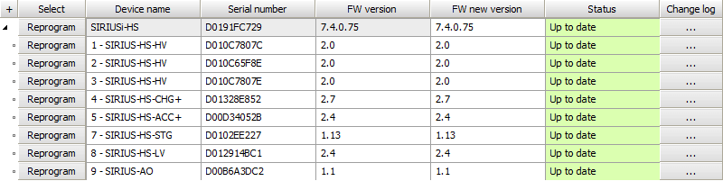
Go to Settings → Update. If the firmware package is not yet selected, click the three-dot button and navigate to the folder containing the firmware file.


Select the device you want to upgrade and start the firmware upgrade by pressing the Upgrade button. A window will appear indicating that the upgrade process has started.


Wait until the software completes the upgrade, then close the window. After the upgrade is finished, the device status will turn green and display “Up to date.”

What are the advanced options in settings?
Here you can find advanced options for different areas such as hardware, visuals, math, diagnostics, and analysis.
Hardware


Dewesoft devices
USB Speed Limit Warning (per slice): This option allows you to define the USB speed limit for each slice. If the speed is exceeded, a warning will appear in the channel setup.


SoftSync Sample Rate Limit – Defines the maximum sample rate limit when two devices are synchronized using SoftSync (e.g., KRYPTON). The software synchronization accuracy is approximately 2–10 ms, which is sufficient for simple temperature measurements. This synchronization method does not require additional hardware.
Always Enable USB System Driver – If the Dewesoft USB system driver is disabled in the Device Manager, it will be automatically re-enabled.
Disable EtherCAT Interface – Enable this option if you do not want Dewesoft to scan or use EtherCAT devices.
Set SIRIUS Sample Rate Limit to 204.8 kHz – Sets the maximum sample rate to 204.8 kHz for DEWE-43, SIRIUS, SIRIUS-CD, and SIRIUS-HD devices.
Decode 2nd Part of the IRIG Time Frame – DS-Clock can now also decode the second part of the IRIG signal. Once this option is enabled, a new channel will appear in the system monitor.


Channel Sample Rate Behavior – Allows you to define how the channel sample rate behaves in relation to the global sample rate.


Disable HW Sample Rate Dividers – Disables hardware dividers and uses software sample rate dividers instead.
Amplifiers
When working with sensors that include a TEDS chip, scanning is required. If this option is enabled, the system will scan for the TEDS chip only once. If the option is disabled, the system will continuously scan for TEDS sensors.


Once the sensor is read, the serial number, amplifier settings, and sensor sensitivity are displayed.
Write Dewesoft TEDS Templates Only – Limits writing to Dewesoft-defined TEDS templates.
Shunt Calibration Error Limit (applies to STG and STGM modules) – Shunt calibration is used to measure and correct the resistance of strain gauges. Since shunt calibration requires setting several configurations and measuring the results, it takes some time. The Shunt Calibration Error Limit defines the maximum allowed deviation from the target value.
If the deviation is more than 2%, the result is invalid.
If the deviation is within 2%, the result is accepted.


Capacity Check Error Limit (applies to CHG modules) – When charge sensors are connected, a capacity check can be performed. First, enter the known target value for capacity. After entering the value, press Check. Dewesoft will then generate a sine wave and measure the actual capacity. Once the procedure is complete, Dewesoft will display both the measured capacity and the error. If the error exceeds the defined limit, it will be shown in red.


Enable Calibration by Shunt – This option allows you to trust the shunt calibration result and use it for further measurements.


Disable Additional Software High-Pass Filter if Below Calculation Limit – When this option is enabled and the limit of the software high-pass filter (SW-HPFilter) is reached, no additional SW-HPFilter is calculated. The SW-HPFilter is typically required for slow accelerometers to display very low frequencies while ignoring offset.
If this option is disabled and the SW-HPFilter limit is reached, the filter will still be calculated at the closest possible value. In such cases, the offset may be more noticeable than the loss of very low frequencies.
This setting is intended for specific sensors, such as MSI-ACC (or DSI-ACC). Some accelerometers operating in IEPE mode may still produce an offset even if the amplifier includes a hardware high-pass filter (HW-HPFilter). To remove this offset, a software high-pass filter is calculated using the formula:
Frequency (SW-HPFilter) = Frequency (HW-HPFilter) / 10
In most cases, this works without issues. However, for MSI-ACC sensors with an HW-HPFilter at 0.08 Hz, the SW-HPFilter calculation may reach its limit depending on the sample rate, making further calculation impossible.
Always Keep TEDS Header Serial Number – Ensures that the TEDS header always retains the sensor’s serial number.
Allow Changing Offset When Scaling Is Disabled – Allows users to modify the offset value even when scaling is turned off.
CAN
CAN can be set to Acknowledge Mode by default whenever a new device is detected.


We can view the CAN operation mode when selecting the settings of a measurement device.
Read-only mode – The DAQ device can only read messages from CAN data.


Read/Write/Acknowledge mode – The DAQ device can both read and transmit CAN data. To add a new transmit channel, click the icon inside the red square.


Digital filters
If the desired filter is not available on the connected device, the first available filter will be selected:
OFF
Anti-aliasing (IIR)
AAF (Zero-phase distortion)
Ring-free
AAF (Zero-Phase Distortion) Transition Width
Auto-adjust – Sets the AAF to 16% transition width (up to a 1:100 sample rate ratio).
User-defined – Ensures the transition band is always achieved, though this may result in higher computational load.
Enable Alias-Free Filtering on SIRIUS-HS
This option enables an additional AAF with a cutoff frequency at 80 kHz when the sample rate is equal to or above 160 kHz, or a cutoff frequency of fs/2 when the sample rate is below 160 kHz.
Visuals


Graphics
The Use asynchronous buffer for GDI calls option allows the software to use a dedicated thread for graphics processing.


In the XY graph, we can define the delta cursor angle offset and the number of decimal places for the delta cursor.
In Image 145, the delta cursor offset is set to 0, and the decimal places are set to 5. As a result, the values of dX and dY are displayed with five decimal places, and the angle is shown as 60°.
In Image 146, the decimal places of dX and dY are increased to 10, and the angle offset is set to 5°, making the total angle 65°


3D Graph
Show miss distance calculation
Max vertex count – Defines the number of points generated for the 3D graph widget. The number of points can be limited if system memory is running low.
GPS Map
Max samples shown – Defines the maximum number of samples that will still be displayed on the GPS map.
Scope
Memory size – Defines the scope trigger memory size per channel.
Maximum picture size
Maximum number of pictures
Math
In the math section, you can enable a sharper anti-aliasing filter in order tracking.


Diagnostics


When we are on the Measure screen, we can access system performance information by pressing the shortcut CTRL+SHIFT+P. This view can also be set as the default part of the screen.


The System Info default page can be set to either Performance or Details.
If measurement hardware is connected to the computer, we can also display debug system channels (such as sync error, IRIG time, VCXO values, etc.). These settings can also be viewed under the System Monitor in Channel Setup.


Analysis


Here, you can select a synchronous channel as the output for sound replay in Analysis mode (0 = none, 1 = first sync channel, etc.).
For example, let’s say we are measuring signals from five channels, and we want to use the third one (AI 3) as the default channel for sound replay.


To set the third channel (AI 3) for sound replay, simply enter the number 3 in the checkbox.


After storing and replaying the data file, we will see that the third channel (AI 3) is now the default output channel for sound replay.


Use relative event time by default for new setups – With a new setup, all events will use relative time by default. If this option is disabled, the default time is absolute. The time type can also be changed during measurement by right-clicking on the event and selecting Change time display.


NET


Starting TCP/IP port for MU data connection – It is possible to define the starting port on the master measurement unit.
For example, if the starting port is 8998, this port will be used by the first measurement unit. The second measurement unit will use 8997.
The port 8999 is fixed and cannot be changed. This port must be open on both master and slave units.
The port 1999 is used for the Dewesoft Launcher and must also be open.
Allow NET connection in master mode – If Dewesoft is configured as a Master client or Master measurement unit, you can define which clients are allowed to connect:
None
View client only
Master or view client
Cross Trigger
Selected network interface for the cross trigger – Select the network card used for the NET system.
Multicast group – Configure the same IP multicast address on both master and slave units for the cross trigger to function correctly.
Cross trigger delay – Defines the maximum allowed network delay for the cross trigger.
Setup Screen Connection
Keep client connection on view change – Requires Dewesoft 64-bit connection. The master PC remains connected to slave units even when they are not selected, ensuring a smoother transition between units.
Default protocol for connection:
VNC (UltraVNC) – The default password is set to a, but for better security, Dewesoft allows you to change it.
RDP (Windows Remote Desktop) – The remote desktop offers two authentication options:
Use Windows credentials – If the master unit was previously connected to a slave unit and the connection was saved, this option can be used.
User name and password – Required if the master unit is connecting to a slave unit for the first time.
Events
It is possible to define which events will be shown on the master client or master measurement unit.
How to import license?
The license for measuring with DewesoftX is included in the device (usually the PROF version). Once connected to the USB port, the device acts as a dongle.
The license for analyzing is free! DewesoftX can be installed on any computer, and stored data files can be opened, recalculated, and exported.
Additional licenses may be required for certain plugins. These licenses can also be written directly into the Dewesoft® device. To test plugins, you can request a 30-day trial license.

In the Licensing section, you can view your Active licenses, create a new license, or import an offline license (*.lic file format).
Offline registration
If your measurement PC has internet access, you can register directly from within DewesoftX. If not, DewesoftX will automatically prompt you to complete offline registration.
Enter your license key and press the arrow next to the license number field.


If no DAQ devices are connected to the computer, the license will be generated only for the MAC address of the PC.


DewesoftX will automatically connect to the internet and complete registration online. If there is no internet connection, DewesoftX will prompt you to register offline.


In offline mode, DewesoftX will create a *.lic file, which you must save to your computer.
Copy the created license (*.lic) file from the measurement computer and transfer it to a computer with internet access. Then, visit the Dewesoft homepage and select Registration.
Upload (drop) the *.lic file into the registration window to complete the process.


When you upload your license file, the following window will appear. Please download the generated file.
Save the new “.lic” file and overwrite the existing “.lic” file on the measurement computer.


Finally, restart DewesoftX and select Import license. Then, import the *.lic file that you downloaded from the website.


Evaluation license
To receive a fully functional 30-day evaluation license for DewesoftX software, complete and submit the form below. Fields marked with an asterisk (*) are required. Please provide a valid email address where the evaluation license will be sent.


Write license to Dewesoft devices
If a software license is already installed on your PC, you can also write the license to Dewesoft measurement devices. This allows the devices to be used with another computer as well.


If a license is already written on the measurement device, a warning message will appear. You can choose to overwrite the existing license with a new one.


Page 1 of 19