

What You’ll Learn 🧩
Discover DewesoftX’s new C++ Signal Processing Plugin framework—how it abstracts DCOM interfaces and simplifies creating powerful plugins
Install required tools: Visual Studio, DewesoftX development version, C++ Plugin template via VSIX
Recreate the classic “latch math” example in C++—building on knowledge from the C++ Script course
Use the VS template wizard to create a plugin project, configure metadata, and remove sample code
Develop plugin logic with modern C++: process input channels, generate output channels, and integrate with DewesoftX settings or UI
Extend your plugin with custom GUI elements and handle runtime events like button clicks
Improve code reliability with debugging support and unit testing of plugin functionality using Google Test
Manage settings serialization: save and load user-defined parameters across sessions
Export/import plugin bundles easily, with the convenience of cross-system sharing and deployment
Course overview
The Developing Custom Signal Processing Plugins course equips software engineers to build advanced, C++-based processing modules that integrate seamlessly into DewesoftX. Unlike legacy plugins, this modern framework offers powerful C++ capabilities with easier development and debugging workflows
You’ll begin by setting up your development environment—installing Visual Studio and the DewesoftX development version, and adding the official C++ Processing Plugin template via the VSIX installer. With these foundations, you’ll generate a new plugin project, configure project metadata, and remove sample boilerplate code.
The course then walks through reimplementing core logic such as “latch math” using modern C++. You’ll learn to read data from input channels, execute custom processing pipelines, produce output channels, and tie into DewesoftX configuration settings and GUI components. The framework supports full custom GUI integration, enabling developers to create user-facing control elements that interact directly with plugin behavior.
Further modules will get you comfortable with debugging techniques, unit-test patterns using Google Test, and managing plugin settings across sessions. You’ll also learn how to package your code into deployable bundles that automatically register with DewesoftX, facilitating easy sharing and deployment across teams.
By the end of the course, you’ll be well-versed in the full lifecycle of plugin development—from creating templates, writing robust processing logic, designing interactive interfaces, and deploying usable plugins for end users. This training builds directly on the previous C++ Script Pro course and deepens your ability to extend DewesoftX with high-performance C++ modules.
Introduction to C++ signal processing plugin
Extending Dewesoft in the past was a daunting task. Writing a proper plugin required extensive knowledge of how the software operated under the hood.
C++ Script demonstrated that it doesn’t have to be this way—that writing plugins could (and should) be an easy process. The issue with the legacy plugin system was that it was written too generically. It gave programmers great power over Dewesoft, but even writing a trivial plugin from scratch was extremely difficult.
The Processing Plugin aims to solve this problem. It uses Dewesoft’s DCOM interface to access its internals but abstracts the interaction away from the programmer—almost entirely. The result is that, while you still retain direct control over Dewesoft (as with the more bare-bones plugin system), you can now write plugins almost as easily as with C++ Script—only with far more powerful debugging tools than C++ Script could ever offer.
You can take an arbitrary number of input channels, process the data using modern C++, output the results to output channels, modify Dewesoft settings, and much more.
The C++ Processing Plugin also allows you to create your own user interface, which—together with your C++ code—is compiled into an external library and automatically recognized and loaded by Dewesoft. This makes it easy to export and import your plugin for use on other computers.
How to install the Dewesoft plugin template?
To start using the C++ Processing Plugin, you must have the Visual Studio IDE installed on your system. We have chosen Visual Studio because it offers a powerful combination of developer tools and debugging capabilities.
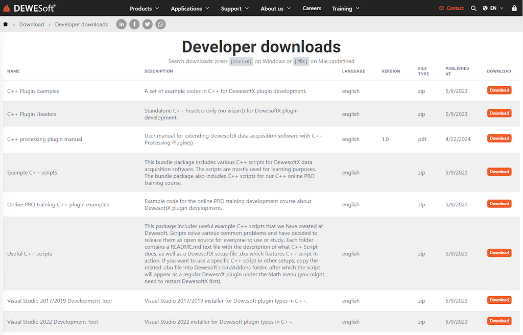
You can download the DewesoftX Processing Plugin Template from the Dewesoft website under:
Support > Downloads > Developers > C++ Plugin.
Note: You must be logged in to access the C++ Plugin section.
After downloading the template, simply double-click the file, and the VSIX installer will guide you through the installation process.
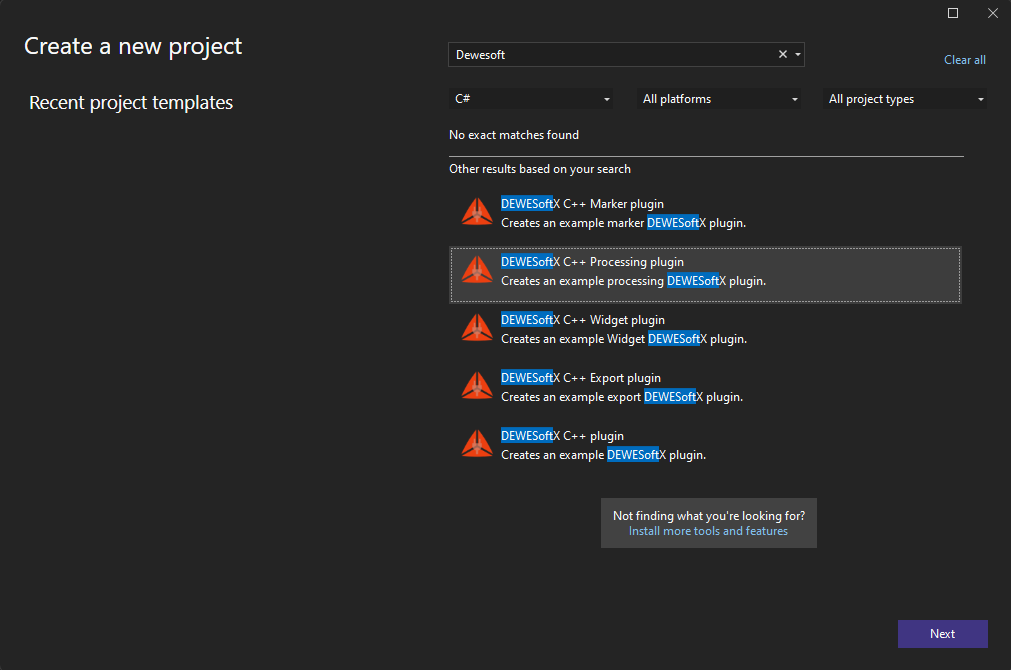
Once the Visual Studio Development Tool is installed, you will be able to access the Dewesoft plugin template by opening the New Project window and selecting the DewesoftX Processing Plugin template.

Example: latch math
In this Pro Training, we will once again recreate the Latch Math example, as we did in the C++ Script Training. Therefore, completing and understanding the C++ Script Pro Training is a prerequisite for this tutorial, as we will build upon that knowledge. This approach ensures that the parallels between C++ Script and the Processing Plugin are as clear as possible.
To follow along effectively, we recommend that you first read the corresponding tutorial available at:
Dewesoft > Training > PRO Training > Develop > C++ Script,
and prepare the same setup described in the chapter titled Example: Latch Math.
Example: new C++ processing plugin
To create a new C++ Processing Plugin, click the Project button in File > New > Project. Select the DewesoftX C++ Processing Plugin Template as your template. After clicking the OK button, a wizard window will appear to guide you through the plugin creation process.

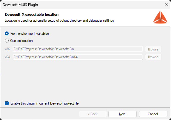
Since your plugin will be integrated into Dewesoft, it needs to know Dewesoft’s installation location. You can define this location manually, and the installer will create system variables: DEWESOFT_EXE_X86 (for 32-bit Dewesoft) and DEWESOFT_EXE_X64 (for 64-bit Dewesoft). In this case, Visual Studio must be restarted to refresh its environmental variable state.

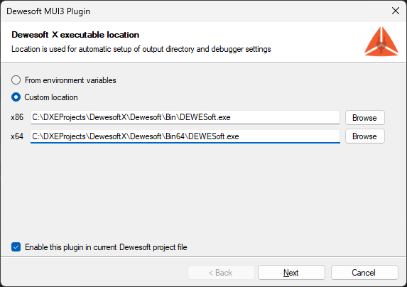
Once these system variables are set, the installer will automatically detect them in future sessions, so you won’t need to specify the location again.
If you'd prefer to set these variables manually, you can do so via the System Properties window (open it by pressing the Windows key and searching for Edit the system environment variables). Under the Advanced tab, click Environment Variables.
After clicking the Next button, the following window will appear, allowing you to set plugin information such as the plugin name, ownership, and version.

Plugin name - The name that will be seen in Dewesoft.
Description - Short description of your plugin.
Vendor - Company that created the plugin.
Copyright - Owner of the plugin.
Major version - Sets the initial major version. The value should change when a breaking change occurs (it's incompatible with previous versions).
Minor version - Sets the initial minor version. The value should change when new features and bug fixes are added without breaking compatibility.
Release version - Sets the initial release version. The value should change if the new changes contain only bugfixes.
All fields are optional except for the Plugin Name, and they can all be modified later in the code.
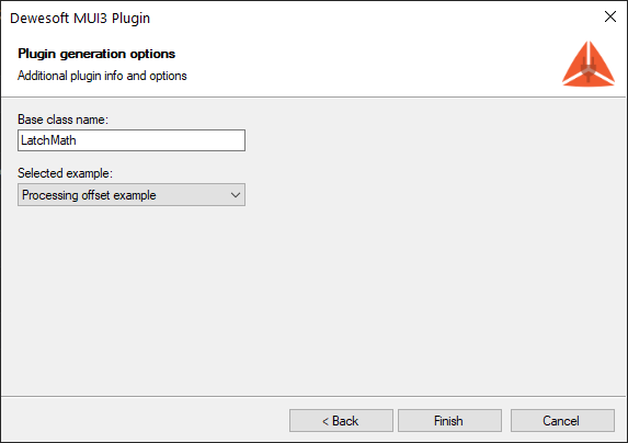
Clicking Next will take you to the final window, where you define the Base Class Name. This will be used as a prefix for the class and project names. After entering the base class name, click Finish, and the wizard will generate the plugin template according to your settings.
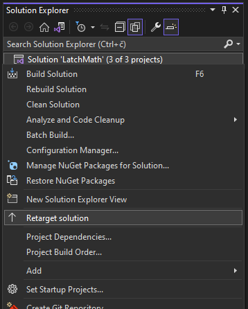
If you encounter Error MSB8036: The Windows SDK version 'sdk_version' was not found, you need to retarget your solution to use the version installed on your system. To do this, right-click your solution node in the Solution Explorer, then select Retarget Solution.

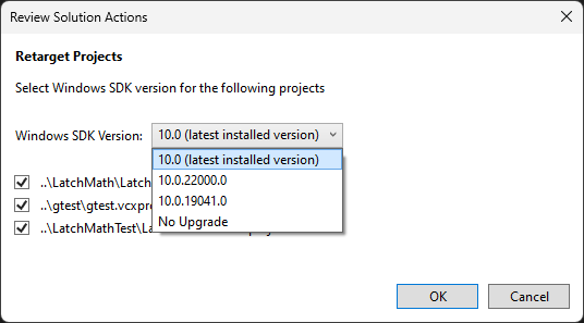
In the Retarget Solution window, choose the option Latest installed version.

Structure of the solution
When a new C++ Processing Plugin project is created, the wizard generates the basic files and folder structure necessary for development. In the image below, you can see a tree view of the collapsed project structure. In our case, LatchMath refers to the name used as the Base Class.


LatchMathPlugin - The actual plugin implementation
LatchMathPluginTest - Solution for writing unit tests for LatchMathPlugin.
gtest - Google test library, required by LatchMathPluginTest for unit testing your plugin. This project should not be modified.
As mentioned earlier, our plugin implementation resides in the LatchMathPlugin project. It includes:
Files for writing the plugin logic. A dewesoft_internal folder with helper methods used to interface with Dewesoft. An icon.png file for the plugin icon. The core files: plugin. plugin.h and plugin.cpp serve as the entry points for your plugin, and contain the base class with the same name as defined with These last two serve as entry points for your plugin and contain the base class (with the same name as defined in the wizard). Here, you'll connect input channels, define output channels, and implement the core plugin logic—similar to how it's done in C++ Script. You can also define additional plugin properties and handle setup variable persistence.
The UI folder is divided into two subfolders: Setup UI: Used in the plugin's setup form. Settings UI: Accessed via Options > Settings > Extensions, where your plugin is listed. Both folders include: An .xml file for defining the user interface, a .h header file for method and variable declarations .cpp file for implementing the UI logic
After generating the project, you’re ready to extend Dewesoft. But before writing the plugin logic, let’s check how it integrates by default. Start the program using the F5 shortcut or by pressing the Start button in the middle of Visual Studio's main toolbar.


Once Dewesoft loads, your plugin will be accessible in the main toolbar under Measure mode via:
Ch. Setup > More... > Latch math - scalar
As you’ll see, it already includes some example elements that were automatically added to the user interface.


Example I: removing sample code
It is important to keep in mind that C++ uses header files (recognized by the .h extension) in addition to source files (with the .cpp extension). Header files are used to declare classes, variables, and methods, while their definitions and implementations are written in the corresponding source files.
When we first create a new plugin, the LatchMathPlugin project also contains a sample plugin that adds an offset to the input signal. Before writing our own code, we will remove this sample code, as it is not needed for the plugin we’ll develop in this tutorial.
Our ui/setup/setup_window.h should look like this:
1#pragma once
2#include "generated/ui/setup/plugin_setup_window.h"
3#include "plugin.h"
4
5class LatchMathSetupWindow : public LatchMathSetupWindowBase
6{
7  public:
8    virtual void bindEvents() override;
9    virtual void initiate() override;
10};
and ui/setup/setup_window.cpp should look like this:
1#include "StdAfx.h"
2#include "ui/setup/setup_window.h"
3
4using namespace Dewesoft::MUI;
5
6void LatchMathSetupWindow::bindEvents()
7{
8}
9
10void LatchMathSetupWindow::initiate()
11{
12}
Let’s also simplify the ui/setup/setup_window.xml file by removing everything except the most basic structure.
1<?xml version="1.0" encoding="utf-8"?>
2<Window xmlns="https://mui.dewesoft.com/schema/1.1">
3</Window>
Next, we’ll remove any remaining sample code from the plugin.h and plugin.cpp files. Only the essential methods that will be used later should be retained.
The plugin.h file should now look like this:
1#pragma once
2#include "interface/plugin_base.h"
3
4enum class OffsetType
5{
6    Fixed = 0,
7    Dynamic = 1,
8};
9
10class LatchMathModule : public Dewesoft::Processing::Api::Advanced::Module
11{
12  public:
13    static void getPluginProperties(PluginProperties& props);
14
15    void configure() override;
16    void calculate() override;
17
18    void updateSetup(Setup& setup) override;
19
20    void connectInputChannels(InputChannelSlots& slots) override;
21    void mountChannels(OutputChannels& fixed, OutputChannels& dynamic) override;
22};
23
24class LatchMathSharedModule : public Dewesoft::Processing::Api::Advanced::SharedModule
25{
26};
and the plugin.cpp file should look like this.
1#include "StdAfx.h"
2#include "plugin.h"
3
4namespace adv = Dewesoft::Processing::Api::Advanced;
5using namespace Dewesoft::Utils::Dcom::Utils;
6
7void LatchMathModule::getPluginProperties(PluginProperties& props)
8{
9    props.name = "Latch math - scalar";
10    props.description = "Pro Tutorial example.";
11    props.pluginType = PluginType::application;
12    props.hasProjectSettings = false;
13}
14
15void LatchMathModule::connectInputChannels(InputChannelSlots& slots)
16{
17}
18
19void LatchMathModule::mountChannels(OutputChannels& fixed, OutputChannels& dynamic)
20{
21}
22
23void LatchMathModule::configure()
24{
25}
26
27void LatchMathModule::calculate()
28{
29}
30
31void LatchMathModule::updateSetup(Setup& setup)
32{
33}
With these changes complete, we are ready to begin writing our Latch Math plugin.
Example I: code
Let's start by implementing the logic of our plugin. This is done by editing the plugin.h and plugin.cpp files of the project. Much like in C++ Script, these files contain classes with methods that Dewesoft automatically calls when appropriate (e.g., when measuring starts, when it stops, when the setup is saved, etc.).
First, let's create the two input channels required by our plugin. Unlike in C++ Script, where channels can be added via the user interface, in the Processing Plugin we have to define them manually. This is done by modifying the plugin.h and plugin.cpp files. In the plugin.h, we define the two input channels as public variables of the Module class.
1class LatchMathModule : public Dewesoft::Processing::Api::Advanced::Module
2{
3  public:
4    // ...
5    ScalarInputChannel criteriaChannelIn;
6    ScalarInputChannel inputChannelIn;
7};
Note: The channel types are ScalarInputChannel, just like in C++ Script. This is intentional. Channels in the Processing Plugin have interfaces similar to those in C++ Script, so if you're already familiar with C++ Script, transitioning to Processing Plugin channels should be straightforward.
In plugin.cpp, we reserve two input slots (seen in the top-left panel of the settings window) to hold our channels and connect them with the variables we just defined. This is done by modifying the connectInputChannels() method:
1void LatchMathModule::connectInputChannels(InputChannelSlots& slots)
2{
3    slots.connectChannel("Input channel", &inputChannelIn, ChannelTimebase::Synchronous);
4    slots.connectChannel("Criteria channel", &criteriaChannelIn, ChannelTimebase::Synchronous);
5}
We specify that our two input slots will be named "Input channel" and "Criteria channel", and that their timebases will be synchronous.
To get the code to compile, we also need to modify the getPluginProperties() method. Here we configure general plugin behavior—such as how many channels it accepts, where it appears in Dewesoft, whether it has a settings form, and so on. For our purposes, the most relevant property is inputSlotsMode , which determines how the plugin handles multiple inputs.
1void LatchMathModule::getPluginProperties(PluginProperties& props)
2{
3    props.name = "Latch math - scalar";
4    props.description = "Pro Tutorial example.";
5    props.pluginType = PluginType::application;
6    props.hasProjectSettings = false;
7    props.inputSlotsMode = InputSlotsMode::multiple;
8}
After compiling the project, you should be able to find the plugin under the "More..." menu. When you add it, you will see the two input slots we prepared.


Next, let’s define the variables that will control the behavior of our latch math logic. In plugin.h , we add public variables for the criteria limit and edge type. To improve clarity, we also create a custom enum for the edge type.
1enum edgeTypes
2{
3    RisingEdge = 0,
4    FallingEdge = 1
5};
6
7//...
8
9class LatchMathModule : public Dewesoft::Processing::Api::Advanced::Module
10{
11  public:
12    // ...
13    double criteriaLimit = 0;
14    edgeTypes edgeType = RisingEdge;
15};
mountChannels
Next, let's add some output channels to our plugin. Again, in C++ Script this was done by clicking on the UI, but here we have to do it all by hand. First let's add a variable that will hold our output channel to plugin.h:
1class LatchMathModule : public Dewesoft::Processing::Api::Advanced::Module
2{
3  public:
4    // ...
5    ScalarOutputChannel outputChannel;
6};
To register the output channel with Dewesoft, we use the mountChannels() method. Here we define basic channel properties, such as the name seen by the user, the unique channel index, and the output type. Since the channel is defined as a ScalarOutputChannel it will output scalar values.
We also need to set the timebase of the output channel. We do this by mounting the channel with the mountSyncChannel() function if we want the timebase to be synchronous, mountAsyncChannel() for asynchronous timebase or mountSingleValueChannel() if we want the timebase to be a single value. In our example, the output channel should be of an asynchronous type because we do not know exactly when a new sample will be added.
As you can see from the code snippet below we can mount channel as fixed or dynamic channel. The difference between the two is that Fixed must always contain a constant number of channels, while Dynamic may contain a different number of channels every time the mountChannel() method is called.
1void LatchMathModule::mountChannels(OutputChannels& fixed, OutputChannels& dynamic)
2{
3    fixed.mountAsyncChannel("Latch", 0, &outputChannel);
4}
configure
The configure() method gets called every time before the measurement is started. This is the place to set the final settings dependent on and regarding channels.
Here we set the output channels' expectedAsyncRate and can also change the output channels' name, unit and description.
Another important thing to be set here is the properties of the resampler.
1void LatchMathModule::configure()
2{
3    resampler.blockSizeInSamples = 1;
4    resampler.samplingRate = ResamplerSamplingRate::Synchronous;
5    resampler.futureSamplesRequiredForCalculation = 1;
6
7    outputChannel.setExpectedAsyncRate(5);
8}
Let’s briefly explore how the resampler works:
resampler
The C++ Processing Plugin resamples all input channels to a common sample rate—so that they share the same timestamps. In C++ Script, this is handled automatically, with every input channel resampled to the timebase of the first assigned channel. In the Processing Plugin, however, we have more control.
The sampling rate can be:
Synchronous - all the samples will be spaced equidistantly based on the acquisition sample rate;
SingleValue - the input channels only have one sample as an input, and the calculate() function will get called once every couple hundred milliseconds; and
AsynchronousSingleMaster - the samples get resampled to the asynchronous rate of the master channel. To set the master channel we need to call
setMasterChannel()function like so:resampler.setMasterChannel(&inputChannelIn);
You can also define how many samples to receive during each calculate() call via blockSizeInSamples . property, if we choose it to be 1 then the calculation will be sample-based and we only receive one sample per calculate() call, but if we set it higher then we receive a block of samples every time.
If you need access to past or future samples, use: futureSamplesRequiredForCalculation or pastSamplesRequiredForCalculation .
calculate
The calculate() method is called repeatedly during Measure mode. Here is where the actual logic of your plugin is implemented. This is where you safely read from and write to the channels.
1void LatchMathModule::calculate()
2{
3    float currentSampleCriteriaChannel = criteriaChannelIn.getScalar(0);
4    float nextSampleCriteriaChannel = criteriaChannelIn.getScalar(1);
5
6    // check if the two samples from Criteria channel are on different sides of Latch criteria
7    bool crossedRisingEdgeCriteria = currentSampleCriteriaChannel <= criteriaLimit && nextSampleCriteriaChannel >= criteriaLimit;
8    bool crossedFallingEdgeCriteria = currentSampleCriteriaChannel >= criteriaLimit && nextSampleCriteriaChannel <= criteriaLimit;
9
10    // if user set the type of edge to rising edge and the Criteria channel crossed it
11    // or user set the type of edge to falling edge and the Criteria channel crossed it
12    if ((crossedFallingEdgeCriteria && edgeType == FallingEdge) || (crossedRisingEdgeCriteria && edgeType == RisingEdge))
13    {
14        // add the value of the next sample from Input channel to the Latched channel
15        float value = inputChannelIn.getScalar(1);
16        outputChannel.addScalar(value, inputChannelIn.getTime(1));
17    }
18}At this point, the core logic of the latch math plugin is complete. However, there is a significant issue: users cannot modify any settings. This means the criteria limit is always 0, and we’re always detecting the rising edge!
To fix this, we’ll create a user interface that allows users to change the criteria limit and edge type valu
Example I: creating custom UI
We are now ready to start creating the UI for Latch Math. We’ll begin by examining the existing UI for Latch Math that is integrated into Dewesoft. It can be found under:
Measure mode → Math → Add math → Latch value math.
Keep in mind that this is a basic tutorial, so we’ll keep things simple.


Remember that in our getPluginProperties() method, we defined our module to have two input slots. This is the first difference compared to the built-in Latch Math module. Additionally: The Output value will be set to Actual by default, and users will not be allowed to change it. However, users will be able to: Choose whether the latch condition is triggered on a rising or falling edge. Change the criteria limit.
To implement this, we’ll use the following controls: TextBox: A control for user-editable text input, where the user can enter the criteria limit. Label: A control for displaying static, read-only text. We will pair this with the TextBox to make the input field more descriptive. ComboBox: A drop-down menu that lets users choose between rising and falling edge detection.
For layout purposes, we will visually organize settings using: CaptionPanel: A layout control that provides a titled section. Grid: A layout type that arranges its child controls in rows and columns, allowing structured placement.
The user interface is defined in the ui/setup/setup_window.xml file using simple XML-like syntax. We will break the XML code into smaller parts to make it easier to explain and understand. Before we begin writing the code, let’s open the UI preview window called MUI Designer. It allows you to see a live preview of your design. You can open it from: View → Other Windows → MUI Designer (Dewesoft)
In the image below, you can see our final user interface in the MUI Designer. The preview updates automatically when you change the code. When you run the plugin in Dewesoft, the UI will appear and behave exactly as it does in the preview.


Let’s go through the XML code piece by piece:
1<?xml version="1.0" encoding="utf-8"?>
2<Window xmlns="https://mui.dewesoft.com/schema/1.1">
3  <CaptionPanel Title="Latch criteria settings">
First, we write the code to add the CaptionPanel to the UI.


1  <Grid PaddingLeft="5">
2      <Grid.ColumnDefinitions>
3        <ColumnDefinition Width="170"/>
4        <ColumnDefinition Width="100%"/>
5      </Grid.ColumnDefinitions>
6      <Grid.RowDefinitions>
7        <RowDefinition Height="20"/>
8        <RowDefinition Height="20"/>
9        <RowDefinition Height="10"/>
10        <RowDefinition Height="20"/>
11        <RowDefinition Height="20"/>
12        <RowDefinition Height="100%"/>
13      </Grid.RowDefinitions>
Inside the panel, we define a Grid layout that splits the UI into five rows. We only use one column, as all the elements will be stacked vertically.
The column will have a fixed width of 170 pixels.


1  <Label Grid.Column="0" Grid.Row="0" Text="Criteria limit" />
2      <TextBox Grid.Column="0" Grid.Row="1" Name="latchCriteriaEdit" Text="0" />
3      <Label Grid.Column="0" Grid.Row="3" Text="Edge type" />
4      <ComboBox Grid.Column="0" Grid.Row="4" Name="edgeTypeCBox" />
5    </Grid>
6  </CaptionPanel>
7</Window>
Finally, we add the components themselves. Elements should be aligned and visually grouped:Related items (e.g., the "Criteria limit" Label and TextBox) should be positioned close together to emphasize their relationship.


Example I: handling events
We have now designed the UI components needed for our example, but they don't do anything yet. To bring them to life, we need to introduce events into our code (e.g., Click, CheckedChanged, etc.). To create an event, all you need to do is define a method with the same signature as the control’s event handler and then bind it to the corresponding control.
Event handlers are declared in the header file. Below, you can see the declaration of the event handlers that will be executed when their respective events are triggered.
This section of code should be placed in the private section of the ui/setup/setup_window.h file. In our case, we want to add two event handlers: when user changes the Criteria limit, and when he changes the edge type.
1class LatchMathSetupWindow: public LatchMathSetupWindowBase
2{
3  // ...
4  private:
5      void onLatchCriteriaEditChanged(Dewesoft::MUI::TextBox& editBox, Dewesoft::MUI::EventArgs& args);
6      void onEdgeTypeCBoxChanged(Dewesoft::MUI::ComboBox& cBox, Dewesoft::MUI::EventArgs& args);
7};
Since a component can have multiple event handlers bound to the same event, we use the += operator to add an event handler and the -= operator to remove it.. Events should be bound inside the bindEvents() method. The code for how to bind events to our controls can be found in the ui/setup/setup_window.cpp file.
1void LatchMathSetupWindow::bindEvents()
2{
3    latchCriteriaEdit.OnTextChanged += mathEvent(&LatchMathSetupWindow::onLatchCriteriaEditChanged);
4 edgeTypeCBox.OnChange += mathEvent(&LatchMathSetupWindow::onEdgeTypeCBoxChanged);Next, we implement the actual event handler functions. These are responsible for setting the relevant variables in the Module class, which we access via a special variable called module.
Event handler implementations should be placed in the ui/setup/setup_window.cpp file.


The first event handler is triggered when the text is edited in the component marked with a red square in the image above. This sets the criteriaLimit property of the module. Since latchCriteriaEdit is a text box, the value read from it is a string, and we must convert it to a number before assigning it to thecriteriaLimit variable.
1void LatchMathSetupWindow::onLatchCriteriaEditChanged(Dewesoft::MUI::TextBox& editBox, Dewesoft::MUI::EventArgs& args)
2{
3    module->criteriaLimit = std::stod((std::wstring) latchCriteriaEdit.getText());
4}

The second event handler is triggered when the user selects an option in the component marked with the red square in the other image. This updates the edgeType property of the module.
1void LatchMathSetupWindow::onEdgeTypeCBoxChanged(Dewesoft::MUI::ComboBox& cBox, Dewesoft::MUI::EventArgs& args)
2{
3    module->edgeType = edgeTypes(edgeTypeCBox.getSelectedIndex());
4}
Initialization
We also need to populate the edgeTypeCBox with values and initialize all components with appropriate default settings. This should be done in the initiate() method in the ui/setup/setup_window.cpp file, as shown below.
1void LatchMathSetupWindow::initiate()
2{
3    edgeTypeCBox.clear();
4    edgeTypeCBox.addItem("Rising");
5    edgeTypeCBox.addItem("Falling");
6}
Example I: output result
We are now ready to test our plugin. You can do this by running the plugin—press F5 on your keyboard—and navigating to the Ch. Setup tab. Then click More and select the Latch Math – Scalar button. A window like this should appear:

Remember the setup we previously created and saved in Dewesoft (at the start of the C++ Script Pro Training)?
We’re going to use that setup now.
Go to the Setup files tab and double-click the setup you wish to load. The loaded setup should include the two signals created earlier and a blank Latch Math – Scalar window.
Next, assign the signals to the Input and Criteria channels. Set the Criteria Limit, and choose whether you want to detect the latch condition on the rising or falling edge.
Your setup should now look like this:

Now switch to the Measure tab, where you will see a visual representation of the latch operation.
To get the output shown in the image below, we turned off the Interpolate asynchronous channels option in the Drawing Options of the recorder setup. This setting helps better demonstrate that our values are truly being “latched.”

In Image 20, you can observe that each time the sine signal crosses 0 on the rising edge, the output channel latches the current value of the time signal.
The output value represents the exact time at which the sine signal passed through zero.
You can now switch the edge type to falling edge and set the Criteria Limit to 0.5 for a different test case.


Modifying example I
We have created a working plugin for performing latch math. In the previous sections, we took advantage of the C++ Processing Plugin to allow multiple input channels, thereby simplifying the code. Now, let’s modify the plugin to more closely replicate the latch math setup found in Dewesoft.
A clear starting point is the input channels on the left-hand side of the setup window. To modify this behavior, we need to look at a class we’ve previously ignored in plugin.h/.cpp files the SharedModule class.
Module vs. SharedModule
Upon examining the plugin.h file, file, you’ll notice it contains two classes: Module – which we’ve modified previously, and SharedModule – which we’ve not yet used.


As seen in other Dewesoft applications (e.g., FFT Analysis), users can select multiple input channels using checkboxes next to available channels. Each selected input channel spawns a new instance of the Module class. These instances operate independently, except that certain shared settings (via the updateSettings() function, discussed shortly) can be copied across them.
In some cases, it’s useful to have either a shared overview of all Module nstances or shared settings across them. This is where the SharedModule cclass becomes essential. It maintains an overview of every Module instance created in the application and can be accessed by all of them. Every new plugin has one SharedModule class instance available globally to all its modules.

If we revisit the Latch Value Math setup in Dewesoft, we observe that the criteria channel is set only once, regardless of how many input channels are selected. This behavior is achieved by placing the criteria channel inside the SharedModule class. Each checked input channel then corresponds to its own Module instance.
Limit input channels to one:
Set the inputSlotsMode property to allow only a single input channel, or simply omit it, as single is the default.
1void LatchMathModule::getPluginProperties(PluginProperties& props)
2{
3    // ...
4    props.inputSlotsMode = InputSlotsMode::single;
5}
Use the criteria channel via the SharedModule:
In plugin.h , define a new variable in the SharedModule class to hold the criteria channel.
1class LatchMathSharedModule: public Dewesoft::Processing::Api::Advanced::SharedModule
2{
3  public:
4    void connectInputChannels(InputChannelSlots& slots) override;
5
6  private:
7    ScalarInputChannel criteriaChannelShared;
8};
Connect the channel in plugin.cpp: Link this variable to a slot with a unique name, so it can be accessed later.
1void LatchMathSharedModule::connectInputChannels(InputChannelSlots& slots)
2{
3    slots.connectChannel("Criteria channel", &criteriaChannelShared, ChannelTimebase::Synchronous);
4}
Share the channel with each Module instance:
Modify the connectInputChannels() method in the Module class to receive the criteria channel from SharedModule.
1void LatchMathModule::connectInputChannels(InputChannelSlots& slots)
2{
3    slots.connectChannel("Input channel", &inputChannelIn, ChannelTimebase::Synchronous);
4    slots.useSharedModuleChannel("Criteria channel", &criteriaChannelIn);
5}
This allows the code inside the configure() and calculate() methods to remain unchanged, as they now operate with the updated, shared criteria channel.
Next, update ui/setup/setup_window.xml to add a ComboBox for selecting the criteria channel. You’ll also need to: Add a new column to the Grid layout. Properly group UI components for logical alignment. With these changes, the UI should now reflect the additional ComboBox.
1<?xml version="1.0" encoding="utf-8"?>
2<Window xmlns="https://mui.dewesoft.com/schema/1.1">
3  <CaptionPanel Title="Latch criteria settings">
4    <Grid PaddingLeft="5">
5      <Grid.ColumnDefinitions>
6        <ColumnDefinition Width="140"/>
7        <ColumnDefinition Width="30"/>
8        <ColumnDefinition Width="120"/>
9        <ColumnDefinition Width="100%"/>
10      </Grid.ColumnDefinitions>
11      <Grid.RowDefinitions>
12        <RowDefinition Height="20"/>
13        <RowDefinition Height="20"/>
14        <RowDefinition Height="10"/>
15        <RowDefinition Height="20"/>
16        <RowDefinition Height="20"/>
17        <RowDefinition Height="100%"/>
18      </Grid.RowDefinitions>
19
20      <Label    Grid.Column="0" Grid.Row="0" Text="Criteria channel"/>
21      <ComboBox Grid.Column="0" Grid.Row="1" Name="criteriaChannelCBox" />
22      <Label    Grid.Column="2" Grid.Row="0" Text="Criteria limit" />
23      <TextBox  Grid.Column="2" Grid.Row="1" Name="latchCriteriaEdit" Text="0" />
24      <Label    Grid.Column="0" Grid.Row="3" Text="Edge type" />
25      <ComboBox Grid.Column="0" Grid.Row="4" Name="edgeTypeCBox" />
26    </Grid>
27  </CaptionPanel>
28</Window>
With the code above we now create the UI that looks like this.


With the new ComboBox in place, implement the following:
Declare the event handler in setup_window.h :
1class LatchMathSetupWindow: public LatchMathSetupWindowBase
2{
3    // ...
4    void onCriteriaChannelCBoxChanged(Dewesoft::MUI::ComboBox& cBox, Dewesoft::MUI::EventArgs& args);
5}
Every input channel has a designated input slot, we connect the input channel to the slot in the connectInputChannels() and we can then access the slot by searching for it by the unique slot name we defined earlier. So, the definition in ui/setup/setup_window.cpp looks like this:
1void LatchMathSetupWindow::onCriteriaChannelCBoxChanged(Dewesoft::MUI::ComboBox& cBox, Dewesoft::MUI::EventArgs& args)
2{
3    sharedModule->getInputSlot("Criteria channel").assignChannel(criteriaChannelCBox.getSelectedItem());
4}
Inside the handler, access the module using sharedModule , locate the input slot using its unique name, and assign the selected channel to it.
Bind the event in the bindEvents() method:
1void LatchMathSetupWindow::bindEvents()
2{
3    // ...
4    criteriaChannelCBox.OnChange += mathEvent(&LatchMathSetupWindow::onCriteriaChannelCBoxChanged);
5}
By default, the new ComboBox will appear empty, even if Dewesoft has available channels. To populate it:
Update the initiate() method in setup_window.cpp to manually populate the ComboBox with available channels.
1void LatchMathSetupWindow::initiate()
2{
3    // ...
4
5    criteriaChannelCBox.clear();
6    ChannelSlot& slot = sharedModule->getInputSlot("Criteria channel");
7    for (std::string& channelName : availableChannelsFor(slot))
8        criteriaChannelCBox.addItem(channelName);
9}
The availableChannelsFor() method automatically filters channels based on the slot's requirements. Since we connected a scalar and synchronous input channel to the criteriaChannel, the function returns only compatible channels present in Dewesoft at setup time.
The setup of the plugin with assigned input channels will now look like this


Example II: vector latch math explanation
At approximately this point in our C++ Script Pro Training, we decided to add support for vector input channels to our script. Why not try doing the same for our Processing Plugin?
To continue following along with the Pro Training, load the setup file we created in
C++ Script > Example II: Vector Latch Math. While you're at it, take a moment to refresh your understanding of the different channel types available in Dewesoft. All of that knowledge transfers seamlessly to the Processing Plugin!
From example I to example II
Let's start with the project created in Example I and modify it to support a vector channel.
The first thing we need to do is update the input and output channels to be vector channels. This is simply done by changing the channel declarations from scalar to vector types. The criteria channel remains unchanged.
1class LatchMathModule : public Dewesoft::Processing::Api::Advanced::Module
2{
3  public:
4    // ...
5    VectorInputChannel inputChannelIn;
6    VectorOutputChannel outputChannel;
7}
We also need to modify the connectChannel() call for our vector channel, as we no longer want it to be synchronous. Vector channels always have either an asynchronous or single-value timebase, and the connectChannel() function is intelligent enough to detect that we are connecting a vector channel.
1void LatchMathModule::connectInputChannels(InputChannelSlots& slots)
2{
3    slots.connectChannel("Input channel", &inputChannelIn);
4    slots.useSharedModuleChannel("Criteria channel", &criteriaChannelIn);
5}
calculate
To move from Example I to Example II, we only need to update the logic for reading from and writing to vector channels. To read from the InputChannelIn , we now use the .getVector() method, and to write to OutputChannel we use the .addVector() function.
We will also move the logic for checking whether the criteria limit has been crossed into a new helper function to improve code readability. This function should be declared in the plugin.h file:
1class LatchMathModule : public Dewesoft::Processing::Api::Advanced::Module
2{
3public:
4    // ...
5    bool checkCrossedEdgeCriteria(float currentSampleCriteriaChannel, float nextSampleCriteriaChannel);
6};
And implemented in plugin.cpp like this:
1bool LatchMathModule::checkCrossedEdgeCriteria(float currentSampleCriteriaChannel, float nextSampleCriteriaChannel)
2{
3    bool crossedRisingEdgeCriteria = currentSampleCriteriaChannel <= criteriaLimit && nextSampleCriteriaChannel >= criteriaLimit;
4    bool crossedFallingEdgeCriteria = currentSampleCriteriaChannel >= criteriaLimit && nextSampleCriteriaChannel <= criteriaLimit;
5
6    return (crossedFallingEdgeCriteria && edgeType == FallingEdge)
7        || (crossedRisingEdgeCriteria && edgeType == RisingEdge);
8}
The calculate()function can now be simplified to call this helper function.
1void LatchMathModule::calculate()
2{
3    float currentSampleCriteriaChannel = criteriaChannelIn.getScalar(0);
4    float nextSampleCriteriaChannel = criteriaChannelIn.getScalar(1);
5
6    bool crossedEdge = checkCrossedEdgeCriteria(currentSampleCriteriaChannel, nextSampleCriteriaChannel);
7
8    if (crossedEdge)
9    {
10        adv::Vector value = inputChannelIn.getVector();
11        outputChannel.addVector(value, inputChannelIn.getTime());
12    }
13}
configure
Since our output channel is now a vector channel, we must set its axis to match the input vectors. We do this in the configure() method by copying the axis from the input channel using the .copyAxis() method and providing the input channel’s axis as the parameter.
Our input channel is of vector type and asynchronous, so we also need to adjust the resampler settings. We'll set the samplingRate to AsynchronousSingleMaster. This is necessary because Dewesoft resamples all input channels to a common sample rate. However, vector channels cannot be resampled to a synchronous rate, as that would be extremely memory- and time-intensive. Therefore, we define inputChannelIn as the master channel. This ensures that criteriaChannelIn is resampled to match the timestamps of inputChannelIn.
1void LatchMathModule::configure()
2{
3    resampler.blockSizeInSamples = 1;
4    resampler.samplingRate = ResamplerSamplingRate::AsynchronousSingleMaster;
5    resampler.setMasterChannel(&inputChannelIn);
6    resampler.futureSamplesRequiredForCalculation = 0;
7
8    outputChannel.axes[0].copyAxis(inputChannelIn.axes[0]);
9    outputChannel.setExpectedAsyncRate(5);
10}
We must also configure the expectedAsyncRate for our asynchronous output channel. Here's why:
Expected async rate per second
Much like in C++ Script, if our module has asynchronous output channels, we must define their expected sample rate. This tells Dewesoft how much memory to allocate. You can think of it as an approximation of how many samples per second you expect to add to the channel. We can change the value of this setting in configure() method using:outputChannel.setExpectedAsyncRate(inputChannel.expectedAsyncRate()).
If we know that the output rate closely mirrors that of an input channel, this is an easy way to estimate it. You may also define the rate manually, but keep in mind:
If the value is too high, Dewesoft may reserve too much memory.
If it's too low, you risk losing important data.
You don’t need to specify the exact value, but it should be correct within an order of magnitude.
If you forget to setsetExpectedAsyncRate()for even one asynchronous output channel, the plugin will not load.
Example II: saving and loading settings
You might have noticed that whenever you reopen Dewesoft, the settings in our plugin reset to their default values. It would be helpful if we could store the plugin's configuration and automatically reload it whenever an existing setup is loaded.
In our case, we want to save information such as the criteria limit and whether we're detecting a rising or falling edge.
The first parameter is the name under which your setting is saved. This parameter should be unique for every setting, must not contain any whitespace, and must start with a letter.
The second parameter is the actual value to be stored.
The optional third parameter specifies what the default value should be.
To update our settings in the plugin.cpp file, we use the updateSetup() method, as shown in the code below. This method is responsible for reading stored values whenever a setup is loaded, and for writing those values whenever the setup is saved in Dewesoft.
1void LatchMathSetupModule::updateSetup(Setup& setup)
2{
3    setup.update("criteriaLimit", criteriaLimit, 0.0);
4
5    int intEdgeType = int(edgeType);
6    setup.update("edgeType", intEdgeType, 0);
7    edgeType = edgeTypes(intEdgeType);
8}We also need to ensure that the input fields in the UI are populated with the correct values every time a setup is loaded. This is done in the initiate() method located in the ui/setup/setup_window.cpp file:
1void LatchMathSetupWindow::initiate()
2{
3    // ...
4    if (slot.getAssignedChannel())
5        criteriaChannelCBox.setSelectedIndex(criteriaChannelCBox.getIndexOf(slot.getAssignedChannel().name()));
6
7    latchCriteriaEdit.setText(std::to_string(module->criteriaLimit));
8    edgeTypeCBox.setSelectedIndex(int(module->edgeType));
9}
Example II: debugger
Because the C++ Processing Plugin uses the Visual Studio IDE, it supports powerful debugging tools. These tools help you find semantic errors, inspect variable values in real-time, set breakpoints, add watches to track variable changes during program execution, and much more.
If we now run our plugin by pressing F5 on the keyboard, load the setup we created for testing, and try assigning the channels as shown in Image 27, we quickly encounter an error message.


We quickly get an error message.


The error is thrown in the CalculateBlock() method, which means it originates from the calculate() method of our plugin. To investigate, we’ll set a breakpoint inside this method, start the plugin again using F5, and repeat the process of assigning the channels. When program execution reaches our breakpoint, we can inspect each line of code to determine which one is causing the crash. To step through the code line by line, use the F10 key (this steps over function calls).
We will now attempt to locate the error using the Visual Studio Debugger.
As we step through the code, we notice that at line 46, we attempt to access a sample at position 1 , but it fails.


The first thing we should check is whether we actually have access to this future sample. Specifically, we need to inspect
1configure()method. Here, we see that
1futureSamplesRequiredForCalculationis set to 0. This means we are trying to access a sample that does not yet exist — which explains the error.
To fix the issue, we simply need to set
1futureSamplesRequiredForCalculationto 1. After making this change, the plugin should work as intended.
Example II: unit testing
One of the most important stages of plugin development is testing. Unit testing is a software testing method that verifies the functionality of your plugin by running predefined test cases and checking if the results are correct. The C++ Processing Plugin makes it easy to write and run automated tests, which significantly shortens both development and testing time.
With this approach, we can test each component independently without needing to start Dewesoft. All tests are defined in the plugin_test.cpp file, which can be found inside the LatchMathTest solution. We will create two simple unit tests to evaluate our checkCrossedEdgeCriteria() method. If the returned value matches the expected value, the unit test will mark it as "PASSED."
Here are a few examples of unit tests:
1TEST(LatchMathModule, CheckCriteriaLimitRisingEdge)
2{
3    LatchMathModule p;
4
5    p.criteriaLimit = 0.5;
6    p.edgeType = RisingEdge;
7
8    EXPECT_TRUE(p.checkCrossedEdgeCriteria(0.49, 0.51));
9    EXPECT_TRUE(p.checkCrossedEdgeCriteria(0, 1));
10    EXPECT_TRUE(p.checkCrossedEdgeCriteria(0, std::numeric_limits<float>::infinity()));
11    EXPECT_TRUE(p.checkCrossedEdgeCriteria(-std::numeric_limits<float>::infinity(), std::numeric_limits<float>::infinity()));
12    EXPECT_FALSE(p.checkCrossedEdgeCriteria(0.51, 0.49));
13    EXPECT_FALSE(p.checkCrossedEdgeCriteria(1, 0));
14    EXPECT_FALSE(p.checkCrossedEdgeCriteria(0, -std::numeric_limits<float>::infinity()));
15    EXPECT_FALSE(p.checkCrossedEdgeCriteria(0.49, 0.4999999));
16}
17
18TEST(LatchMathModule, CheckCriteriaLimitFallingEdge)
19{
20    LatchMathModule p;
21
22    p.criteriaLimit = 0.2;
23    p.edgeType = FallingEdge;
24
25    EXPECT_TRUE(p.checkCrossedEdgeCriteria(0.21, 0.19));
26    EXPECT_TRUE(p.checkCrossedEdgeCriteria(1, 0));
27    EXPECT_TRUE(p.checkCrossedEdgeCriteria(std::numeric_limits<float>::infinity(), 0));
28    EXPECT_TRUE(p.checkCrossedEdgeCriteria(std::numeric_limits<float>::infinity(), -std::numeric_limits<float>::infinity()));
29    EXPECT_FALSE(p.checkCrossedEdgeCriteria(0.19, 0.21));
30    EXPECT_FALSE(p.checkCrossedEdgeCriteria(0, 1));
31    EXPECT_FALSE(p.checkCrossedEdgeCriteria(-std::numeric_limits<float>::infinity(), 0));
32    EXPECT_FALSE(p.checkCrossedEdgeCriteria(0.19999999, 0.219999));
33}
You can use Visual Studio's Test Explorer to run and monitor the results of your unit tests. To open the Test Explorer, go to Test > Windows and click on Test Explorer.

Tests can be executed by clicking the Run All option in the Test Explorer. Once the testing is complete, a green checkmark will appear next to the name of each test that passed, and a red cross will indicate any test that failed.


Example II: output
If you now start your plugin and set the Input channel to AI 1/AmplFFT and the Criteria channel to sine(1), as shown in the image below,

")
you will be able to see the output vectors displayed on a 3D graph. A new vector is output every time the sine(1) signal crosses the value 0 on the rising edge.

As illustrated, whenever sine(1) exceeds the Criteria limit, the plugin outputs the latest vector sample from the input channe AI1/AmplFFT to the Output channel.
Import/export
In this Pro Training, we have created a very useful plugin that we might want to use in other setups or on different computers. The C++ Processing Plugin compiles your plugin into an external library, which can then be inserted into any Dewesoft installation around the world.
Your C++ Processing Plugin is packaged into files with the .ilk and .prc extensions. These files contain the instructions Dewesoft uses to execute your plugin’s functionality. To export the plugin, you first need to locate these files. They are typically found in: DEWESoftX\DEWEsoft\Bin\Addons — if the plugin was built using the 32-bit version of Dewesoft, or DEWESoftX\DEWEsoft\Bin64\Addons — if it was built using the 64-bit version.
Inside this directory, you'll find a folder named after your plugin's base class name.


To import your plugin into another Dewesoft installation, simply copy the .prc file into the Addons folder of the target system. Dewesoft will then automatically recognize and load the plugin during startup.
Comparison with other ways of extending Dewesoft
At this point, you likely have a solid understanding of how to use the C++ Processing Plugin. However, the C++ Processing Plugin is just one of many ways to extend Dewesoft to fit your specific needs. It can be somewhat confusing to determine whether it’s the best solution for your particular task.
In this section, we’ll briefly compare different approaches and highlight a few pros and cons of each, which will hopefully help you choose the most suitable tool for your application.
| Extention | Description |
|---|---|
| Formula | If you want to manipulate channels in a simple way, the Formula module is usually the best one to start experimenting with. Because of its ease of use, it can serve as a great starting point for quick prototyping, and it is usually good enough for most typical problems (signal generation, simple manipulation of data in channels, etc.). |
| C++ Script | During its development, we mainly envisioned C++ Script as a tool to create custom math modules that you could export and use just like standard Dewesoft modules. C++ Script is probably a good second step after your approach with Formula modules gets too complicated, too cluttered, or, in the worst case, you cannot figure out how to solve the problem with them. |
| Plugins | If you want to develop anything other than math modules, or if you tried creating a module with C++ Script and it proved to not be fast or powerful enough, or if you want to create a completely custom GUI for your module, Plugins are the right way to go. With Dewesoft Plugins you get access to entire Dewesoft from your code, including direct access to buffers behind channels, making Plugins incredibly fast compared to C++ Script. |
| Sequencer / DCOM | Sequencer and DCOM are slightly different than the other 3 approaches mentioned in this section. Regardless, they serve a very useful purpose and deserve to be mentioned here: they are used to automate a person clicking on different parts of the Dewesoft UI. The difference among them is that with Sequencer you can create sequences by dragging and dropping graphical blocks (requiring little to no experience with programming) while with DCOM you need to use a programming language. Sequencer is easier to use, but you get much more control with DCOM. |
| Extention | PROS | CONS |
|---|---|---|
| Formula | - The most intuitive of all the approaches, very simple to use.- Integrated fully into Dewesoft meaning no set up required to get running. | - Input channels are fixed in the formula, making reusability a lot of work.- While it supports combining arbitrarily many input channels, it always produces just one output channel.- Poor support for non-scalar channels. |
| C++ Script | - Dewesoft setups look much nicer as you (usually) only need one C++ Script to solve a problem that would require a bunch of Formula modules- Reusability and generality of your module: you can hide the code from the end-user and only expose the Published setup tab.- It can work with an arbitrary amount of input and output channels. | - Requires familiarity with at least basics of programming in C++.- Difficult to test and debug. |
| Plugins | - Much easier to write nice code with proper unit tests.- Full control over the creation of GUI, access to Dewesoft internals, and blazing fast.- It can be used to create custom export formats, custom visual controls, add support for additional acquisition devices, ...- Made to work with Visual Studio, giving you access to a great debugger, code completion, and other static analysis tools. | - Requires Visual Studio.- Much harder to learn to use than C++ Script. |
| Sequencer / DCOM | - It can be used to create an automated sequence of events in Dewesoft.- Creator of the sequence can hide the details from the end-user, exposing only a simple user interface to control Dewesoft. | / |
Page 1 of 20