

What You’ll Learn 🧩
Understand DewesoftX’s C++ Plugin framework and its ability to extend core functionality
Install the Visual Studio plugin template (VSIX) to enable DewesoftX C++ plugin development
Create your first plugin: the “latch math” example—use two input channels, apply conditions, and output values
Develop custom UIs: build GUI components, use DewesoftBridge for interactive control, and handle events (e.g., button clicks)
Advance to vector-based processing (“vector latch math”), including saving/loading settings, debugging, and testing with unit tests
Integrate with Dewesoft internals: read/write channels, process data in real time, and modify UI dynamically
Debug and unit test your plugin with Visual Studio tools
Export/import compiled plugin bundles for easy distribution across DewesoftX installations
Course overview
The Basic Custom Plugin Development in C++ course empowers developers to build real-time plugins that integrate deeply with DewesoftX. It begins with an introduction to the C++ Plugin architecture, highlighting its ability to access Dewesoft’s internals—channels, UI, settings, and more—through DCOM, enabling full-featured custom modules.
You’ll set up your development environment by installing Visual Studio and the DewesoftX plugin template via a VSIX installer. With that in place, you’ll work through the iconic latch math example: monitoring one channel and outputting values from another based on a threshold condition—useful for scenarios like sampling RPM when a speed threshold is crossed.
The course then covers UI integration: creating custom panels, interactive controls via DewesoftBridge, event handling, and seamless integration with DewesoftX’s visual interface. You’ll later enhance your plugin to support vector-based signal processing (“vector latch math”), along with features like saving/loading settings, debugging in Visual Studio, and writing unit tests to ensure reliability.
Finally, you’ll learn how to package your plugin into a bundled DLL and distribute it—allowing users to import it into any DewesoftX setup. This module lays the foundation for more advanced topics, such as advanced plugin development and custom DAQ driver creation.
Introduction to basic custom plugin development in C++
Do you want to extend Dewesoft on your own? With the help of the C++ Plugin, you can create custom plugins and integrate them into any Dewesoft installation. Since the C++ Plugin has access to Dewesoft's internal functionality, it can do virtually everything Dewesoft can do. You can use any number of input channels, process data using modern C++, output results to output channels, modify Dewesoft settings, and much more!
The C++ Plugin also allows you to create a custom user interface. This interface, together with your C++ code, is compiled into an external library that Dewesoft automatically recognizes and loads. This makes your plugin easy to export and reuse on other computers.
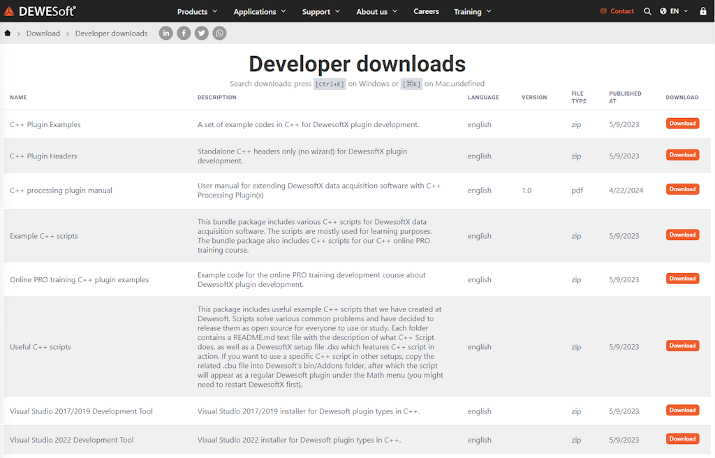
AAll the C++ Plugin examples and setups used in this tutorial are available on the Dewesoft website under:
Support > Downloads > Developers > C++ Plugin
Note: You must be logged in to access the C++ Plugin section.
How to install the Dewesoft plugin template?
To start using the C++ Plugin, you must have Visual Studio IDE installed on your system. We chose Visual Studio due to its robust features and powerful developer tools such as IntelliSense code completion, debugging capabilities, a fast code editor, and easy customization options, among many others.
The Dewesoft plugin for Visual Studio development can be found on the Dewesoft website under:
Support → Downloads → Developers → C++ Plugin. Note: You must be logged in to access the C++ Plugin section. After downloading the plugin, simply double-click the VSIX file, and the installer will guide you through the installation process.

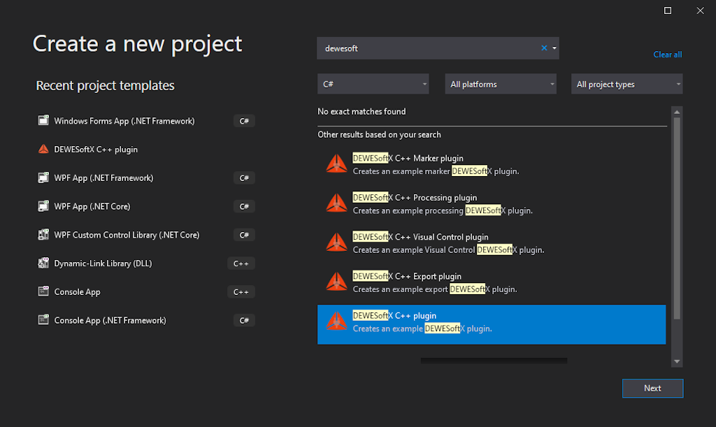
Once the VSIX plugin is installed, you will be able to create a Dewesoft C++ plugin by opening the New Project window and selecting DewesoftX C++ Plugin from the available templates.

Example: latch math
To gain a better understanding of how to work with the C++ Plugin, we will implement a Latch Math module. The Latch Math module outputs the value of one input channel when another input channel crosses a predefined threshold.
An example use case for this module would be monitoring your car's engine RPM when the vehicle reaches 100 km/h. In this case, you would set the first input channel to engine RPM, the second input channel to vehicle speed, and define the threshold criterion as 100 km/h.
By the end of this example, you should have a working module that allows you to:Select two input nnels: One to evaluate the latch criterion. One from which the output values will be captured. Produce an output channel that reflects the latched values.
Signals for testing our module
Before we begin creating the C++ Plugin, let’s first define the two input signals we’ll use to test it.
Open Dewesoft, click the New Setup button, and then click Math.
First Signal – Latch Condition
This signal will serve as the condition for threshold crossing. For testing purposes, we’ll create a 1 Hz sine wave:
Click the Formula button next to Add Math.
From the Signal tab, add the sine function.
Name the signal: "sine(1)". In the formula field, enter:
1sine(1)This signal provides the values that will be captured when the condition is met. We’ll use the current time: Click the Formula button again.
From the Signal tab, add the time function.
Name this signal: "time".
1timeimeOnce both signals are configured, don’t forget to save the setup. This ensures your signals are ready to be used when testing the plugin.
Example: new C++ plugin
Now let’s go back to Visual Studio. To create a new C++ Plugin, click the Project button by navigating to File > New > Project. Select the DewesoftX Plugin Template as your template and enter a name for your project. After clicking the OK button, a wizard window will appear to guide you through the plugin creation process.
Since your plugin will be integrated into Dewesoft, it needs to know the location of the Dewesoft installation. You can either define this location manually, or let the installer create the required system variables for you: DEWESOFT_EXE_X86 (for 32-bit Dewesoft) and DEWESOFT_EXE_X64 (for 64-bit Dewesoft) system variables for us. If the system variables are created during installation, you must restart Visual Studio so that it picks up the updated environment variables.
Once these system variables are set, the installer will automatically locate the Dewesoft directories, and you won’t need to specify the location manually for future projects.
If you prefer to set the variables manually: Press the Windows key and search for Edit the system environment variables. Under the Advanced tab, click Environment Variables. Add the appropriate path under System Variables.
If you have only the 64-bit or 32-bit version of Dewesoft installed, you will only be able to create plugins for that architecture.
After clicking the Next button, a window appears where you can set plugin information such as: plugin name, its ownership, and version.
Plugin name - The name that will be seen in Dewesoft.
Description - Short description of your plugin.
Vendor - Company that created the plugin.
Copyright - Owner of the plugin.
Major version - Sets the initial major version. The value should change when a breaking change occurs (it's incompatible with previous versions).
Minor version - Sets the initial minor version. The value should change when new features and bug fixes are added without breaking compatibility.
Release version - Sets the initial release version. The value should change if the new changes contain only bugfixes.
All fields can be modified later in the code, except the Plugin name, which is mandatory.
Clicking Next again brings up the final wizard window, where you define your Base class name. This base name is used as a prefix for the generated class and project. Once set, click the Finish button to generate the plugin template based on your selections.

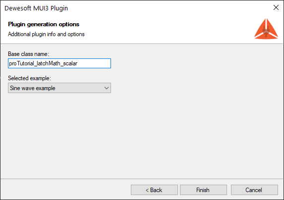
Below the Base class name field, you’ll find a dropdown menu for selecting a code example to include:Sine wave example – Sets everything up to output sine wave values. Empty example – Creates a clean template with no example code. We recommend the Empty example if you are already familiar with Dewesoft plugin development.
When the new C++ Plugin project is created, the wizard generates the necessary files and folder structure. In the image below (not included here), you can see the project tree. The name ProTutorial refers to the text used as the Base class name.


proTutorial_latchMath_scalar - Used for communication with Dewesoft through its DCOM interface and creating the Plugin UI.
proTutorial_latchMath_scalarLib - Your main plugin logic should be defined here. In Example I, we will write plugin logic inside the Plugin project to simplify things.
proTutorial_latchMath_scalarTest - Contains test cases that will be run during unit testing.
gtest - Simple library, required by ProTutorialPluginTest for unit testing your plugin. This project should not be modified.
Once the plugin is created and you stumble upon Error MSB8036: The Windows SDK version sdk_version was not found. You should retarget your solution to use the one you have installed. You can do this by right clicking on your solution node in Solution explorer and selecting Retarget solution.

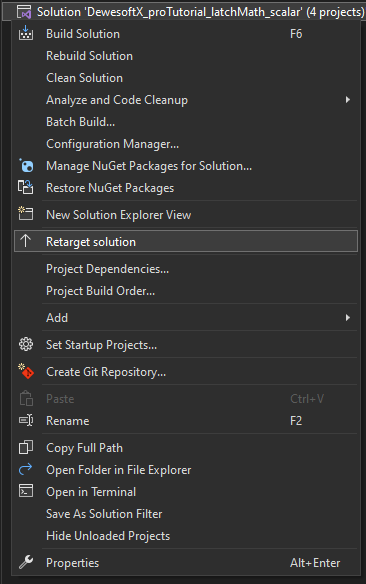
Once the Retarget solution window is opened, you can select "Latest installed version" item.
When our project is successfully generated, we will be able to extend Dewesoft. But before implementing the logic behind our plugin, let's take a look at how our plugin is integrated into Dewesoft. In order to do that, we have to start our program using the shortcut F5 or pressing the Start button in the center of Visual Studio's main toolbar.


After Dewesoft loads, your plugin will appear in Measure mode under: Ch. setup -> ProTutorial. Here, you’ll see the default user interface elements that were added by the wizard-generated example.


Example I: creating custom UI
We are now ready to start creating the plugin for Latch Math. We will begin by examining the existing UI for Latch Math that is already integrated into Dewesoft. It can be accessed via: Measure mode -> Math -> Add math -> Latch value math. Keep in mind that this is a basic tutorial, so we’ll keep things simple. Our goal is to recreate the UI shown on the right side of the picture below. We will not include the channel preview (bottom left corner). Instead, we will allow the user to select one Input channel and one Criteria channel. The Output value will be fixed to Actual by default, so we won’t allow the user to change it. Additionally, we will add Radio Buttons for the user to choose whether the latch condition should be detected on a rising or falling edge.


Two ComboBoxes (controls containing drop-down menus where only one item can be selected), one for selecting the Input channel and the other for the Criteria channel.
One TextBox (a control for user-editable text), allowing the user to enter the Criteria limit.
One Label (a read-only text control) to describe the TextBox.
Two RadioButtons (controls whose Checked property can be toggled by clicking), used to determine whether we are detecting a rising or falling edge.
CaptionPanel (a layout control with a title) to group the Input and Criteria settings.
Grid (a layout type that arranges child controls in rows and columns that can be spanned) to structure the UI layout.
We’re now ready to create the custom user interface for Latch Math. The UI is defined in the setup_window.xml file using a simple, XAML-like syntax. The XML code for the UI will be presented in smaller parts for clarity and explanation. Each snippet will be accompanied by a visual reference showing the result. When the plugin is run, the interface will appear inside Dewesoft.
1<?xml version="1.0" encoding="utf-8"?>
2<Window xmlns="https://mui.dewesoft.com/schema/1.1">
3    <Grid>
4        <Grid.ColumnDefinitions>
5            <ColumnDefinition Width ="170"/>
6            <ColumnDefinition Width ="100%"/>
7        </Grid.ColumnDefinitions>
8        <Grid.RowDefinitions>
9            <RowDefinition Height="100%"/>
10        </Grid.RowDefinitions>
For example, a basic Grid definition splits the UI into two columns. The first column has a fixed width of 170 pixels, while the second column takes up the remaining width of the window. For instance, if the total window width is 500 pixels, the second column will be 330 pixels wide. Upon resizing, the first column remains fixed, while the second adapts to fill the rest of the space. The Grid also contains a single row that occupies the full window height.


1     <CaptionPanel Grid.Column="0" Title="Input">
2            <Grid>
3                <Grid.RowDefinitions>
4                    <RowDefinition Height="20"/>
5                    <RowDefinition Height="100%"/>
6                </Grid.RowDefinitions>
7                <Grid.ColumnDefinitions>
8                    <ColumnDefinition Width="100%"/>
9                </Grid.ColumnDefinitions>
10
11                <Label Text="Input channel" Grid.Row="0" />
12                <ComboBox MarginRight="20" Grid.Row="1" Name="inputChannelName" />
13            </Grid>
14        </CaptionPanel>
Next, we add a CaptionPanel to the first column of our main Grid using Grid.Column="0". Inside the CaptionPanel, a nested Grid is defined with two rows—one for the Label and one for the ComboBox.ComboBox.


1  <CaptionPanel Grid.Column="1" Title="Latch criteria settings">
2            <Grid>
3                <Grid.ColumnDefinitions>
4                    <ColumnDefinition Width="140"/>
5                    <ColumnDefinition Width="30"/>
6                    <ColumnDefinition Width="120"/>
7                    <ColumnDefinition Width="100%"/>
8                </Grid.ColumnDefinitions>
9                <Grid.RowDefinitions>
10                    <RowDefinition Height="20"/>
11                    <RowDefinition Height="20"/>
12                    <RowDefinition Height="10"/>
13                    <RowDefinition Height="20"/>
14                    <RowDefinition Height="20"/>
15                    <RowDefinition Height="100%"/>
16                </Grid.RowDefinitions>
17
18                <Label Grid.Column="0" Text="Criteria channel"/>
19                <ComboBox Grid.Column="0" Grid.Row="1" Name="criteriaChannelName" />
20                <Label Grid.Column="2" Text="Criteria limit" />
21                <TextBox Grid.Column="2" Grid.Row="1" Name="latchCriteria" Text="0"></TextBox>
22                <RadioButton Grid.Column="0" Grid.Row="3" Name="risingEdge" Label="Rising edge" IsChecked="True" />
23                <RadioButton Grid.Column="0" Grid.Row="4" Name="fallingEdge" Label="Falling edge" />
24            </Grid>
25        </CaptionPanel>
26    </Grid>
27</Window>
And lastly, we add the code for filling out the second column of our main Grid. This one is a bit more complex since elements need to be aligned and visually grouped (items that are connected should be closer. e.g. Criteria limit caption Label and TextBox). That is why we have created another Grid element with six rows and four columns, where our components can be inserted.


MUI designer
Until now, we’ve tested the interface inside Dewesoft by running the plugin. However, when editing the UI, it's not necessary to run the plugin every time. Instead, we can use MUI Designer, which provides a live preview of the design. You can find it in: Visual Studio > View > Other windows > MUI Designer (Dewesoft).
In the image below, you can see our finalized user interface displayed in MUI Designer. The preview automatically updates whenever the code is modified. When we run the plugin inside Dewesoft, the UI will appear and behave exactly as shown in the MUI Designer.


Example I: accessing the UI component using C++
We have now created the user interface for our plugin but it is not really doing anything at the moment. We still have to add some functionality to the UI components.
It is important to keep in mind that C++ uses header files (you can recognize them by the .h extension) in addition to source files. Header files are designed to provide information about your class and are used for declaration of variables and methods, while their initialization is done in the source files with .cpp extension. Before writing our own code, we will first remove the sample code as it is not needed. Our setup_window.h should look like this:
1#pragma once
2#include <mui/ds_window.h>
3#include <mui/controls.h>
4#include <mui/layout.h>
5
6class DewesoftBridge;
7
8class SetupWindow : public Dewesoft::MUI::DSWindow
9{
10public:
11    SetupWindow(Dewesoft::MUI::WindowPtr ui, DewesoftBridge& bridge);
12
13private:
14    DewesoftBridge& bridge;
15};
And setup_window.cpp should look like this:
1#include "StdAfx.h"
2#include "setup_window.h"
3#include "dewesoft_bridge.h"
4#include <thread>
5#include <chrono>
6#include <regex>
7
8using namespace Dewesoft::MUI;
9using namespace Dewesoft::RT::Core;
10
11SetupWindow::SetupWindow(WindowPtr ui, DewesoftBridge& bridge)
12    : DSWindow(ui, "ui/setup_window.xml")
13    , bridge(bridge)
14{
15}
Our new components will be declared in setup_window.h file. We usually keep components in the private section of our class. We then forward all the information from the controls and their events to the bridge that will handle all the communication with Dewesoft.
1private:
2    DewesoftBridge& bridge;
3
4    Dewesoft::MUI::ComboBox criteriaChannelCBox;
5    Dewesoft::MUI::ComboBox inputChannelCBox;
6    Dewesoft::MUI::TextBox latchCriteriaTBox;
7    Dewesoft::MUI::RadioButton risingEdgeRButton;
8    Dewesoft::MUI::RadioButton fallingEdgeRButton;
These components are later initialized in setup_window.cpp fwhere we connect them to the actual UI elements by specifying their component names. This is typically done in the class constructor using the Connect method.
1SetupWindow::SetupWindow(WindowPtr ui, DewesoftBridge& bridge)
2    : DSWindow(ui, "ui/setup_window.xml")
3    , bridge(bridge)
4{
5    criteriaChannelCBox = ComboBox::Connect(ui, "criteriaChannelName");
6    inputChannelCBox = ComboBox::Connect(ui, "inputChannelName");
7    latchCriteriaTBox = TextBox::Connect(ui, "latchCriteria");
8    risingEdgeRButton = RadioButton::Connect(ui, "risingEdge");
9    fallingEdgeRButton = RadioButton::Connect(ui, "fallingEdge");
10}
After successfully connecting the UI components, the next step is to retrieve available channels from Dewesoft and populate the ComboBoxes with their names so the user can select them.
For simplicity, we will only use synchronous input channels (i.e., channels where the time between samples is constant). First, we need to access all available channels in Dewesoft and filter out the non-synchronous ones.
To do this, we utilize Dewesoft internals, which are accessible through the DewesoftBridge class (defined in dewesoft_bridge.h and dewesoft_bridge.cpp). Channel information is stored in the bridge's app member variable, which represents the Dewesoft DCOM interface.
We’ll create a function named getSyncChannels() that reads channel data from app, filters the results, and returns only the synchronous channels.
1// dewesoft_bridge.h
2// this method needs to be public
3std::vector<IChannelPtr> getSyncChannels();
4
5// dewesoft_bridge.cpp
6std::vector<IChannelPtr> DewesoftBridge::getSyncChannels()
7{
8    std::vector<IChannelPtr> allSyncChannels;
9
10    app->Data->BuildChannelList();
11    IChannelListPtr channels = app->Data->UsedChannels;
12
13    for (int i = 0; i < channels->Count; i++)
14        if (!channels->GetItem(i)->Async)
15            allSyncChannels.push_back(channels->GetItem(i));
16
17    return allSyncChannels;
18}
Once the getSyncChannels() function is in place, we’re ready to populate the ComboBoxes. We’ll do this in the constructor within setup_window.cpp, immediately after initializing the controls.
The two controls, criteriaChannelCBox and inputChannelCBox, represent the ComboBoxes into which we’ll insert the channel names. To help with this, we’ll define a helper function named void addChannelsToCBox();. This function should be declared as public because we’ll also call it later from within the bridge.
1// setup_window.h
2void addChannelsToCBox();1// setup_window.cpp
2SetupWindow::SetupWindow(WindowPtr ui, DewesoftBridge& bridge)
3 : DSWindow(ui, "ui/setup_window.xml")
4 , bridge(bridge)
5{
6 // member initialization
7 // ...
8 addChannelsToCBox();
9}
10
11void SetupWindow::addChannelsToCBox()
12{
13 criteriaChannelCBox.clear();
14 inputChannelCBox.clear();
15 std::vector<IChannelPtr> allChannels = bridge.getSyncChannels();
16
17 for (int i = 0; i < allChannels.size(); i++)
18 {
19 std::string channelName = allChannels[i]->Name;
20 criteriaChannelCBox.addItem(channelName);
21 inputChannelCBox.addItem(channelName);
22 }
23}Once everything is connected and implemented correctly, launching Dewesoft should show the available channel names when clicking on the ComboBoxes.


Example I: handling events
We have now initialized all the UI components needed for our example, but these components don’t perform any actions yet. To make them functional, we need to introduce event handling into our code (e.g., Click, CheckedChanged, etc.). To create an event, all you need to do is define a method with the same signature as the control’s event handler and bind it to the control.
Event handlers are declared in the header file. Below is an example of how to declare event handlers that will be triggered when specific events occur. These declarations should be placed in the private section in setup_window.h file.
1private
2    // ...
3    void onCriteriaChannelChanged(Dewesoft::MUI::ComboBox& cBox, Dewesoft::MUI::EventArgs& args);
4    void onInputChannelChanged(Dewesoft::MUI::ComboBox& cBox, Dewesoft::MUI::EventArgs& args);
5    void onEditTextChanged(Dewesoft::MUI::TextBox& editBox, Dewesoft::MUI::EventArgs& args);
6    void onRadioGroupChanged(Dewesoft::MUI::RadioButton& radioGroup, Dewesoft::MUI::EventArgs& args);
7}
Since a component can have multiple event handlers bound to the same event, we use the += operator to add event handlers and the -= operator to remove them. This binding can only be done after the variables are connected. In our case, we bind events inside the constructor, immediately after connecting the variables.The code that shows how to bind events to our controls is located in the setup_window.cpp file, as shown below:
1SetupWindow::SetupWindow(WindowPtr ui, DewesoftBridge& bridge)
2    : DSWindow(ui, "ui/setup_window.xml")
3    , bridge(bridge)
4{
5    // member initialisation
6    // adding channel names to ComboBoxes
7    // ...
8    criteriaChannelCBox.OnChange += event(&SetupWindow::onCriteriaChannelChanged);
9    inputChannelCBox.OnChange += event(&SetupWindow::onInputChannelChanged);
10    latchCriteriaTBox.OnTextChanged += event(&SetupWindow::onEditTextChanged);
11    risingEdgeRButton.OnCheckedChanged += event(&SetupWindow::onRadioGroupChanged);
12    fallingEdgeRButton.OnCheckedChanged += event(&SetupWindow::onRadioGroupChanged);
13}
Event handlers themselves are defined in setup_window.cpp file. The following sections explain which handler is triggered based on user actions.


This part of the code is triggered when the user edits the text in the component marked with a red square in the picture above.
1void SetupWindow::onCriteriaChannelChanged(Dewesoft::MUI::ComboBox& cBox, Dewesoft::MUI::EventArgs& args)
2{
3    bridge.setCriteriaChannelName(cBox.getSelectedItem());
4}

This part of the code is triggered if we click on any item (that is not already selected) inside the ComboBox component containing input channel names.
1void SetupWindow::onInputChannelChanged(Dewesoft::MUI::ComboBox& cBox, Dewesoft::MUI::EventArgs& args)
2{
3    bridge.setInputChannelName(cBox.getSelectedItem());
4}

This part of the code is triggered when the user edits the text in the component marked with a red square in the picture above.
1void SetupWindow::onEditTextChanged(Dewesoft::MUI::TextBox& editBox, Dewesoft::MUI::EventArgs& args)
2{
3    bridge.setCriteriaLimit(stof(editBox.getText().toStdString()));
4}

This part of the code is triggered when the user clicks on any item (that is not already selected) in the ComboBox containing input channel names.
1void SetupWindow::onRadioGroupChanged(RadioButton& radioGroup, EventArgs& args)
2{
3    if (SetupWindow::fallingEdgeRButton.getIsChecked())
4        bridge.setEdgeType(FallingEdge);
5    else
6        bridge.setEdgeType(RisingEdge);
7}
Example I: DewesoftBridge
The main purpose of the DewesoftBridgeclass is to enable your plugin to communicate with Dewesoft. It contains functions and events that are triggered at specific moments (e.g., when measuring starts, when it stops, when a setup is saved, etc.). A complete list of functions and events can be found in the dewesoft_bridge.h file. In this section, we will only focus on those required for our plugin to function correctly—the rest will remain unchanged. We will use this class to implement the core logic behind the latch math functionality.
We’ll start by making changes to the dewesoft_bridge.h file here we will declare our methods and variables. For the plugin to function properly, we need: Criteria limit value, channel names and for determining whether we are calculating the rising or falling edge. We will also create getter and setter functions for each of these variables. Since all these variables and methods are only accessed internally within the DewesoftBridge, class, they should be marked as private.
1enum edgeTypes
2{
3    RisingEdge = 0,
4    FallingEdge = 1
5};
6
7class DewesoftBridge
8{
9public:
10    // ...
11
12    /* Declarations of methods we added*/
13    std::vector<IChannelPtr> getSyncChannels();
14
15    void setCriteriaChannelName(std::string name);
16    std::string getCriteriaChannelName();
17
18    void setInputChannelName(std::string name);
19    std::string getInputChannelName();
20
21    void setCriteriaChannel(std::string channelName);
22    IChannelPtr getCriteriaChannel();
23
24    void setInputChannel(std::string channelName);
25    IChannelPtr getInputChannel();
26
27    void setCriteriaLimit(float threshold);
28    float getCriteriaLimit();
29
30    void setEdgeType(edgeTypes type);
31    edgeTypes getEdgeType();
32
33private:
34    // ...
35
36    /* Declarations of methods and variables we added */
37    std::string inputChannelName = "";
38    std::string criteriaChannelName = "";
39    IChannelPtr inputChannel;
40    IChannelPtr criteriaChannel;
41
42    float criteriaLimit = 0;
43    edgeTypes edgeType = RisingEdge;
44
45    int64_t lastPosChecked;
46};
The definitions for the getter and setter functions should be implemented in the dewesoft_bridge.cpp file.
1void DewesoftBridge::setCriteriaChannelName(std::string name)
2{
3    this->criteriaChannelName = name;
4}
5std::string DewesoftBridge::getCriteriaChannelName()
6{
7    return this->criteriaChannelName;
8}
9
10void DewesoftBridge::setInputChannelName(std::string name)
11{
12    this->inputChannelName = name;
13}
14std::string DewesoftBridge::getInputChannelName()
15{
16    return this->inputChannelName;
17}
18
19void DewesoftBridge::setCriteriaChannel(std::string channelName)
20{
21    criteriaChannel = app->Data->FindChannel(channelName.c_str());
22}
23IChannelPtr DewesoftBridge::getCriteriaChannel()
24{
25    return this->criteriaChannel;
26}
27
28void DewesoftBridge::setInputChannel(std::string channelName)
29{
30    this->inputChannel = app->Data->FindChannel(channelName.c_str());
31}
32IChannelPtr DewesoftBridge::getInputChannel()
33{
34    return this->inputChannel;
35}
36
37void DewesoftBridge::setCriteriaLimit(float threshold)
38{
39    this->criteriaLimit = threshold;
40}
41float DewesoftBridge::getCriteriaLimit()
42{
43    return this->criteriaLimit;
44}
45
46void DewesoftBridge::setEdgeType(edgeTypes type)
47{
48    this->edgeType = type;
49}
50edgeTypes DewesoftBridge::getEdgeType()
51{
52    return this->edgeType;
53}
Below are the methods that we need to modify or implement for the plugin to operate correctly:
DewesoftBridge::mountChannels()
The void DewesoftBridge::mountChannels() method is called when your plugin or setup is first loaded. It allows you to create output channels within Dewesoft. In our example, the output channel should be of asynchronous type, since we do not know in advance when a new sample will be added. You will need to set basic channel properties such as: basic channel properties like channel name, base type (synchronous, asynchronous type) and underlying data type.
1void DewesoftBridge::mountChannels()
2{
3    const std::vector<int> chIndexVector = {1};
4
5    outputChannel = pluginGroup->MountChannelEx(pluginGuid, long(chIndexVector.size()), fromStdVec(chIndexVector));
6
7    outputChannel->SetDataType(long(ChannelDataType::Single));
8    outputChannel->Name = "Latch";
9    outputChannel->Unit_ = "";
10    outputChannel->SetAsync(true);
11    outputChannel->ExpectedAsyncRate = app->Data->GetSampleRateEx();
12    outputChannel->Used = true;
13}
Dewesoft::onStartData()
This method is called before each measurement begins. It is used to initialize all variables that will be used during the measurement.
1STDMETHODIMP DewesoftBridge::onStartData()
2{
3    setInputChannel(inputChannelName.c_str());
4    setCriteriaChannel(criteriaChannelName.c_str());
5    lastPosChecked = 0;
6
7    return S_OK;
8}
DewesoftBridge::onGetData()
This method is called repeatedly during Measure mode. It provides a safe context for reading from and writing to channels. You should not perform any time-consuming tasks here, as it could affect performance. The method is marked as STDMETHODIMP, which is required so that Dewesoft can call this function via the DCOM interface. Note: This method processes a block of samples, not individual samples. If you need to access each sample individually, you must implement a loop to iterate over them.
1STDMETHODIMP DewesoftBridge::onGetData()
2{
3    if (!inputChannel || !criteriaChannel)
4        return S_OK;
5
6    // calculate the size of blocks in both channels
7    int blockSizeCriteriaChannel =
8        (criteriaChannel->DBPos - (lastPosChecked % criteriaChannel->DBBufSize) + criteriaChannel->DBBufSize) % criteriaChannel->DBBufSize;
9    int blockSizeInputChannel =
10        (inputChannel->DBPos - (lastPosChecked % inputChannel->DBBufSize) + inputChannel->DBBufSize) % inputChannel->DBBufSize;
11
12    int minBlockSize = min(blockSizeCriteriaChannel, blockSizeInputChannel);
13
14    for (int i = 0; i < minBlockSize - 1; i++)
15    {
16        float currentSampleCriteriaChannel = criteriaChannel->DBValues[lastPosChecked % criteriaChannel->DBBufSize];
17        float nextSampleCriteriaChannel = criteriaChannel->DBValues[(lastPosChecked + 1) % criteriaChannel->DBBufSize];
18
19        // check if the two samples from Criteria channel are on different sides of Latch criteria
20        bool crossedRisingEdgeCriteria = currentSampleCriteriaChannel <= criteriaLimit && nextSampleCriteriaChannel >= criteriaLimit;
21        bool crossedFallingEdgeCriteria = currentSampleCriteriaChannel >= criteriaLimit && nextSampleCriteriaChannel <= criteriaLimit;
22
23        // if user set the type of edge to rising edge and the Criteria channel crossed it
24        // or user set the type of edge to falling edge and the Criteria channel crossed it
25        if ((crossedFallingEdgeCriteria && edgeType == FallingEdge) || (crossedRisingEdgeCriteria && edgeType == RisingEdge))
26        {
27            // add the value of the next sample from Input channel to the Latched channel
28            float value = inputChannel->DBValues[(lastPosChecked + 1) % inputChannel->DBBufSize];
29            outputChannel->AddAsyncSingleSample(value, (lastPosChecked + 1) / app->Data->SampleRateEx);
30        }
31        lastPosChecked++;
32    }
33    return S_OK;
34}Example I: output result
We are now ready to test our plugin. To do this, press F5 on your keyboard to run the plugin. Then go to the Ch. setup tab and click the Latch Math – Scalar button in the main Dewesoft toolbar. A window like the one below should appear.


Remember the setup we created and saved earlier in Dewesoft? We're going to use it now. Go to the Setup files tab and double-click the setup you want to load. The loaded setup should include the two signals we created earlier and a blank Latch Math – Scalar configuration window.
Next, assign the signals to the Input and Criteria channels, set the Criteria limit, and choose whether you're evaluating the rising or falling edge. Your configuration should now look like this:


Now switch to the Measure tab, where you can see a visual representation of the latch output.
To achieve the exact view shown in the image below, disable the Interpolate asynchronous channels option in the Drawing options section of the recorder settings. This helps better illustrate that the values are truly "latched."


In the image above, you can see that every time the sine signal crosses 0 on the rising edge, the output channel records the current value of the time signal. The outputted value represents the exact time at which the sine signal crossed 0.
Now, change the edge type to falling edge and update the Criteria limit to 0.5. The results will now look like this:


Example II: vector latch math explanation
Our Latch Math example currently only supports outputting scalar sample values. But what if we want to latch a vector channel when a specific condition is met? We cannot simply assign a vector channel as our input because our plugin doesn’t yet support handling vector inputs. Fortunately, this issue can be addressed using the C++ Plugin framework, and we will resolve it by modifying our existing plugin.
To identify the necessary changes, let’s take a brief detour and explain the different types of channels in Dewesoft.
Channel types
In Dewesoft, you can think of a channel as a structure that holds a stream of signal data. Channels can be categorized in two primary ways:
Based on their value type, channels can be split into:
scalar, vector, and matrix channels; where each of these could be
real, or complex channels.
For example, if you have a real vector channel, then every sample in the channel is a vector (of equal dimensions) containing real-number values.
Based on their time base, channels can be split into:
synchronous;
asynchronous; and
single value.
Synchronous: The time interval between samples is constant and defined by the acquisition sample rate and the channel’s sample rate divider. Asynchronous: The time between consecutive samples can vary. Single Value: These channels hold only one value per measurement, with no timestamp. Each new sample simply replaces the previous value. To illustrate, the image below shows a sine wave represented using channels with different time bases.
To illustrate, the image below shows a sine wave represented using channels with different time bases.


Signals for testing our module
Now that we’ve clarified the types of channels, let’s return to our task. Just as we initially created scalar channels at the beginning of this training, we will now generate a dummy vector channel to test our updated module. One math module in Dewesoft that produces vector output is the Fourier Transform. Let’s use that. We add a new Fourier transform setup from the Add math drop-down list. We change the Resolution in Calculation parameters section to 256 lines (meaning the output vectors will have 256 elements) and click Ok.

From example I to example II
Now that we have created a working plugin, we are ready to move on to more complex concepts. We will use the project created in Example I and modify it to support a vector channel. Example II will be more complex, so we will need to revise elements that were simplified in Example I.
As previously mentioned, all plugin logic that does not require access to Dewesoft internals should be defined inside the proTutorial_LatchMath_vectorPluginLib project. Although we did not fully follow this principle in Example I, our first step now will be to move all non-Dewesoft logic from DewesoftBridge to proTutorial_LatchMath_vectorPluginLib will be the first thing we will do.
The DewesoftBridge class is used for communicating with Dewesoft internals, which is why it should only contain functions designed for that purpose. To follow this principle, we will create a function for checking whether the criteria limit has been crossed inside proTutorial_LatchMath_vectorPluginLib. IThis function will be declared in the protutorial_latchmath_vector.h file:
1class proTutorial_LatchMath_vector
2{
3public
4    bool checkCrossedEdgeCriteria(float currentSampleCriteriaChannel, float nextSampleCriteriaChannel, float criteriaLimit, int edgeType);
5};
And it will be defined in the protutorial_latchmath_vector.cpp file.
1bool proTutorial_LatchMath_vector::checkCrossedEdgeCriteria(float currentSampleCriteriaChannel,
2                                                            float nextSampleCriteriaChannel,
3                                                            float criteriaLimit,
4                                                            int edgeType)
5{
6    bool crossedRisingEdgeCriteria = currentSampleCriteriaChannel <= criteriaLimit && nextSampleCriteriaChannel >= criteriaLimit;
7    bool crossedFallingEdgeCriteria = currentSampleCriteriaChannel >= criteriaLimit && nextSampleCriteriaChannel <= criteriaLimit;
8
9    if ((crossedFallingEdgeCriteria && edgeType == 1) || (crossedRisingEdgeCriteria && edgeType == 0))
10        return true;
11    else
12        return false;
13}
Next, we need to update the DewesoftBridge::onGetData() method in the dewesoft_bridge.cpp file so that it uses this newly created method.
1STDMETHODIMP DewesoftBridge::onGetData()
2{
3    if (!inputChannel || !criteriaChannel)
4        return S_OK;
5
6    int blockSizeCriteriaChannel =
7        (criteriaChannel->DBPos - (lastPosChecked % criteriaChannel->DBBufSize) + criteriaChannel->DBBufSize) % criteriaChannel->DBBufSize;
8    int blockSizeInputChannel =
9        (inputChannel->DBPos - (lastPosChecked % inputChannel->DBBufSize) + inputChannel->DBBufSize) % inputChannel->DBBufSize;
10
11    int minBlockSize = min(blockSizeCriteriaChannel, blockSizeInputChannel);
12
13    for (int i = 0; i < minBlockSize - 1; i++)
14    {
15        float currentSampleCriteriaChannel = criteriaChannel->DBValues[lastPosChecked % criteriaChannel->DBBufSize];
16        float nextSampleCriteriaChannel = criteriaChannel->DBValues[(lastPosChecked + 1) % criteriaChannel->DBBufSize];
17
18        bool crossedEdgeCriteria = protutorial_latchmath_vector.checkCrossedEdgeCriteria(currentSampleCriteriaChannel,
19                                                                                         nextSampleCriteriaChannel,
20                                                                                         criteriaLimit,
21                                                                                         edgeType);
22        if (crossedEdgeCriteria)
23        {
24            float value = inputChannel->DBValues[(lastPosChecked + 1) % inputChannel->DBBufSize];
25            outputChannel->AddAsyncSingleSample(value, (lastPosChecked + 1) / app->Data->SampleRateEx);
26        }
27        lastPosChecked++;
28    }
29    return S_OK;
30}
Since vector channels are always of the asynchronous type, we also need to rename and adapt the getSyncChannels() method to getAsyncChannels() which will return all asynchronous channels. Don’t forget to update the method name in the dewesoft_bridge.h file as well as in setup_window.cpp where the method is called.
1std::vector<IChannelPtr> DewesoftBridge::getAsyncChannels()
2{
3    std::vector<IChannelPtr> allChannels;
4
5    app->Data->BuildChannelList();
6    IChannelListPtr channels = app->Data->UsedChannels;
7
8    for (int i = 0; i < channels->Count; i++)
9        if (channels->GetItem(i) != outputChannel && channels->GetItem(i)->Async)
10            allChannels.push_back(channels->GetItem(i));
11
12    return allChannels;
13}
Finally, because our Input channel will now be a vector channel, we must modify the addChannelsToCBox() method accordingly. We will update this method so that theinputChannelCBox only accepts vector inputs, while the criteriaChannelCBox only accepts scalar inputs.
1void SetupWindow::addChannelsToCBox()
2{
3    criteriaChannelCBox.clear();
4    inputChannelCBox.clear();
5
6    std::vector<IChannelPtr> allChannels = bridge.getAsyncChannels();
7    for (int i = 0; i < allChannels.size(); i++)
8    {
9        std::string channelName = allChannels[i]->Name;
10        if (allChannels[i]->ArrayChannel)
11            inputChannelCBox.addItem(channelName);
12        else
13            criteriaChannelCBox.addItem(channelName);
14    }
15}
Example II: saving and loading settings
Let's now start modifying our project. The reason for removing the non-Dewesoft logic from the dewesoft_bridge.cpp file will become clear soon, but not just yet.
It can be frustrating to select channels, enter the criteria limit, and choose between rising or falling edge every time you start your plugin in Dewesoft. Fortunately, this is no longer necessary because the C++ Plugin framework allows you to store and retrieve your plugin settings using an XML file. In our case, we need to save the criteria limit, input channel name, and criteria channel name. To store enum settings, we will convert them to integers and save them using the WriteInteger function.
Settings are stored using methods with the Write prefix (e.g. WriteInteger) ), and retrieved using methods with the Read prefix (e.g. ReadInteger). We will use the class member doc which is automatically available. The parameters for Write and Read methods depend on the data type being saved, but the approach can be generalized across data types.
The first parameter is the pointer to the node which Dewesoft uses. This parameter is the same for every type.
The second parameter is the name of XML element under which your setting is saved. This parameter should be unique for every setting.
The third parameter is the actual value to be stored.
The fourth parameter is the default value to be stored if the actual value is not yet initialized.
We will save plugin settings when setup is saved and load them when a new setup is loaded.
Storing our settings inside dewesoft_bridge.cpp file is done in onSaveSetup as seen in the code below.
1void DewesoftBridge::onSaveSetup(const Setup& setup)
2{
3    auto node = setup.getNode();
4    node->write("criteriaLimit_vector", getCriteriaLimit(), 0);
5    node->write("inputChannelName_vector", getInputChannelName().c_str(), "");
6    node->write("criteriaChannelName_vector", getCriteriaChannelName().c_str(), "");
7    node->write("edgeType_vector", getEdgeType(), 0);
8}
Loading our settings in the dewesoft_bridge.cpp file is done as shown in the code below. We must set default values in the in Read methods because onLoadSetup method is also called when a new plugin is created, and the XML elements (within the node vvariable) may not exist yet. These elements are only created when the plugin is saved. Therefore, the names for our input and criteria channels will default to ""until the user selects them in the ComboBox.
1void DewesoftBridge::onLoadSetup(const Setup& setup)
2{
3    const auto node = setup.getNode();
4
5    float criteriaValue = 0;
6    node->read("criteriaLimit_vector", criteriaValue, 0);
7    setCriteriaLimit(criteriaValue);
8
9    node->read("inputChannelName_vector", inputChannelName, "");
10    node->read("criteriaChannelName_vector", criteriaChannelName, "");
11
12    long edgeTypeVectorIndex;
13    node->read("edgeType_vector", edgeTypeVectorIndex, 0);
14    edgeType = edgeTypeVectorIndex == 0 ? RisingEdge : FallingEdge;
15
16    mountChannels();
17}
We will also create a public method that will be used to populate input fields in the SetupWindow class.
1//setup_window.h
2void setSavedValues();1// setup_window.cpp
2
3void SetupWindow::setSavedValues()
4{
5 inputChannelCBox.setSelectedIndex(inputChannelCBox.getIndexOf(bridge.getInputChannelName()));
6 criteriaChannelCBox.setSelectedIndex(criteriaChannelCBox.getIndexOf(bridge.getCriteriaChannelName()));
7 latchCriteriaTBox.setText(std::to_string(bridge.getCriteriaLimit()));
8
9 edgeTypes savedEdgeType = bridge.getEdgeType();
10 if (savedEdgeType == RisingEdge)
11 risingEdgeRButton->setIsChecked(risingEdgeRButton.getIsEnabled());
12 else
13 fallingEdgeRButton->setIsChecked(fallingEdgeRButton.getIsEnabled());
14}These input fields should also be populated every time the plugin user interface is entered so that the user doesn't have to reconfigure the channel names and criteria limit manually.
1void DewesoftBridge::onSetupEnter()
2{
3    setupWindow->addChannelsToCBox();
4    setupWindow->setSavedValues();
5}
Now, when Dewesoft is launched and a saved setup is loaded, the saved values will be restored automatically.
Example II: vector latch math
Now that we understand what Example II is about, we are ready to dive into the main code—specifically, the code for handling vector channels.
To create our Output channel that supports vectors, we must modify how it is mounted in Dewesoft. It will accept an array containing values of type Single.Therefore, we need to set the channel's dimension (property DimCount) to 1. If we wanted our Output channel to support matrix samples, we would set the DimCount property to 2. We also define the size of the vector we want to output. In this method, we initially set the size to 1, but we will update this value later to match the size of the input vectors.
1void DewesoftBridge::mountChannels()
2{
3    const std::vector<int> chIndexVector = {1};
4    outputChannel = pluginGroup->MountChannelEx(pluginGuid, long(chIndexVector.size()), fromStdVec(chIndexVector));
5
6    outputChannel->SetDataType(long(ChannelDataType::Single));
7    outputChannel->Name = "Latch";
8    outputChannel->Unit_ = "";
9    outputChannel->SetAsync(true);
10    outputChannel->ExpectedAsyncRate = 5;
11    outputChannel->Used = true;
12    outputChannel->ArrayChannel = true;
13
14    outputChannel->ArrayInfo->DimCount = 1;
15    outputChannel->ArrayInfo->DimSizes[0] = 1;
16    outputChannel->ArrayInfo->Init();
17}There is one important detail to keep in mind: the ExpectedAsyncRate property of our output channel. This brings us to a brief aside:
Expected async rate per second
If our module includes asynchronous output channels, we must specify their expected rate per second. Think of this as “approximately how many samples per second will be written to this channel.” We can set this value in DewesoftBridge::mountChannels() by modifying the channel's ExpectedAsyncRate. This setting is required because we need to help Dewesoft figure out much memory it needs to reserve for our channel. While we can calculate this value in any way we want, it can be useful if we know the rate of our output channel is somehow going to be connected to the rate of some other input channel, in which case we can simply set the outputChannel->ExpectedAsyncRate to inputChannel->ExpectedAsyncRate.
The DewesoftBridge::onEstablishConnections() method is called when acquisition starts (i.e., when entering ch. setup). In this method, we retrieve the Input and Criteria channels using their names. If the names are not yet set—such as when no channels have been selected in the corresponding ComboBoxes—we skip assigning them.
1STDMETHODIMP DewesoftBridge::onEstablishConnections()
2{
3    setInputChannel(inputChannelName.c_str());
4    setCriteriaChannel(criteriaChannelName.c_str());
5
6    return S_OK;
7}
As previously mentioned, we still need to set the size of the vectors we want to output. This must be done before Dewesoft allocates memory to run our plugin. For this reason, we need to hook into the evPreInitiate event. This event should be added in the plugin_impl.cpp file, along with the corresponding method that will be triggered when the event occurs. The method should also be declared in plugin_impl.h file.
1// plugin_impl.h
2//IPlugin4
3STDMETHODIMP eventBeforeReserveMemory();
4
5// plugin_impl.cpp
6STDMETHODIMP Plugin::raw_OnEvent(enum EventIDs eventID, VARIANT inParam, VARIANT* outParam)
7{
8    // ...
9    switch (eventID)
10    {
11        // ...
12        case evPreInitiate:
13            returnValue = eventBeforeReserveMemory();
14            break;
15        // ...
16    return returnValue;
17}
18
19STDMETHODIMP Plugin::eventBeforeReserveMemory()
20{
21    return bridge.onBeforeReserveMemory();
22}
As seen in the code, the method triggered by evPreInitiate will, in turn, call another method defined in DewesoftBridge. We'll add both the declaration and the implementation of this method to the bridge.
1// dewesoft_bridge.h
2STDMETHODIMP onBeforeReserveMemory();
3
4// dewesoft_bridge.cpp
5STDMETHODIMP DewesoftBridge::onBeforeReserveMemory()
6{
7    if (!inputChannel)
8        return S_OK;
9
10    outputChannel->ArrayInfo->DimCount = 1;
11    outputChannel->ArrayInfo->DimSizes[0] = inputChannel->ArraySize;
12    outputChannel->ArrayInfo->Init();
13    outputChannel->ArrayInfo->AxisDef[0]->Name = inputChannel->ArrayInfo->AxisDef[0]->Name;
14    outputChannel->ArrayInfo->AxisDef[0]->_Unit = inputChannel->ArrayInfo->AxisDef[0]->_Unit;
15
16    outputChannel->ArrayInfo->AxisDef[0]->AxisType = atFloatLinearFunc;
17    outputChannel->ArrayInfo->AxisDef[0]->StartValue = inputChannel->ArrayInfo->AxisDef[0]->StartValue;
18    outputChannel->ArrayInfo->AxisDef[0]->StepValue = inputChannel->ArrayInfo->AxisDef[0]->StepValue;
19
20    return S_OK;
21}
At this point, we have successfully mounted the output channel in Dewesoft, configured its axis values, and updated it to support vector outputs derived from the Input channel. The final task is to actually output vector values to the Output channel.
This will be done inside the onGetData() method. For safety, we include a check to ensure the Input channel or Criteria channel is not nullptr, which could occur if the input was not initialized when a new setup was created. To insert data into the Output channel, we will use the AddAsyncData(...) method, which allows inserting a vector directly into the channel.
1STDMETHODIMP DewesoftBridge::onGetData()
2{
3    if (!inputChannel || !criteriaChannel)
4        return S_OK;
5
6    if (inputChannel->DBDataSize == 0 || criteriaChannel->DBDataSize == 0)
7        return S_OK;
8
9    int blockSizeCriteriaChannel =
10        (criteriaChannel->DBPos - (lastPosChecked % criteriaChannel->DBBufSize) + criteriaChannel->DBBufSize) % criteriaChannel->DBBufSize;
11
12    for (int i = 0; i < blockSizeCriteriaChannel - 1; i++)
13    {
14        float currentSampleCriteriaChannel = criteriaChannel->DBValues[lastPosChecked % criteriaChannel->DBBufSize];
15        float nextSampleCriteriaChannel = criteriaChannel->DBValues[(lastPosChecked + 1) % criteriaChannel->DBBufSize];
16
17        bool crossedEdgeCriteria = protutorial_latchmath_vector.checkCrossedEdgeCriteria(currentSampleCriteriaChannel,
18                                                                                         nextSampleCriteriaChannel,
19                                                                                         criteriaLimit,
20                                                                                         edgeType);
21        if (crossedEdgeCriteria)
22        {
23            double time = criteriaChannel->DBTimeStamp[(lastPosChecked + 1) % criteriaChannel->DBBufSize];
24
25            int posInputChannel = (inputChannel->DBPos - 1);
26
27            // reading vector from channel
28            std::vector<float> results;
29            for (int j = 0; j < outputChannel->ArraySize; j++)
30            {
31                float value = inputChannel->DBValues[posInputChannel * inputChannel->ArraySize + j];
32                results.push_back(value);
33            }
34
35            if (outputChannel)
36                outputChannel->AddAsyncData(fromStdVec(results), time);
37        }
38        lastPosChecked++;
39    }
40    return S_OK;
41}
Example II: debugger
Because the C++ Plugin uses the Visual Studio IDE, it supports highly efficient debugging. It helps you find semantic errors, observe variable values in real time, set breakpoints, add watches on variables to monitor changes, and much more.
Let’s run our plugin by pressing F5 on the keyboard. Then, load the setup we previously created for testing and assign the channels as shown in Image 29.


Next, enter Measure mode in Dewesoft. Almost immediately, we receive an error message.


Upon inspection, we can see that the error is thrown in the OnGetData() method. To debug it, we’ll set a breakpoint inside this method, restart the plugin using F5, and navigate to the Measure tab. When the program reaches the breakpoint, execution will pause, allowing us to inspect the code line by line to determine the source of the crash. Use the F10 key to step through each line (this skips over function calls).
We’ll now use the Visual Studio Debugger to locate the problem.


After a few iterations, we discover that
1posInputChannelhas a value of -1 when the last position of the Input channel is 0. This happens because the data in channels is stored in circular buffers and when we try to access the channel values using the
1inputChannel->1DBValues[...]we get an error.

Now that we’ve identified the root cause of the problem, we can fix it. We modify posInputChannels to first check whether the position of the last received value in the Input channels is 0,If it is, then instead of using -1 we use the last index of the buffer as the correct value to output.
1int posInputChannel = inputChannel->DBPos != 0 ? inputChannel->DBPos - 1 : inputChannel->DBBufSize - 1;Example II: unit testing
One of the most important stages of plugin development is testing. Fortunately, the C++ Plugin framework allows you to run automated unit tests, significantly reducing the time required for validation. Unit testing is a software testing method that verifies your plugin’s behavior by running predefined test cases and checking whether the outputs are correct.
Unit testing is one of the main reasons we separate Dewesoft-specific logic (defined inside DewesoftBridge) from non-Dewesoft logic (defined inside proTutorial_LatchMath_vectorPluginLib).
This separation allows us to test each component independently, without needing to launch Dewesoft. To perform unit tests, set proTutorial_LatchMath_vectorPluginTest as your startup project (right-click it and select Set as Startup Project). We will remove the sample code and only test the necessary functions. All test cases are written in the protutorial_latchmath_vector_item_test.cpp file.
We will create two simple unit tests to verify the checkCrossedEdgeCriteria(...) method. If the returned value matches the expected result, the unit test will output "PASSED".
Below are two examples of unit tests (both are expected to pass successfully).
1TEST_F(proTutorial_LatchMath_vectorItemTest, CheckCriteriaLimitRisingEdge)
2{
3    proTutorial_LatchMath_vector protutorial_latchmath_vector;
4
5    float currentSampleCriteriaChannel = 0.49;
6    float nextSampleCriteriaChannel = 0.51;
7    float criteriaLimit = 0.5;
8    int edgeType = 0; // RisingEdge
9
10    bool crossedEdgeCriteria = protutorial_latchmath_vector.checkCrossedEdgeCriteria(currentSampleCriteriaChannel,
11                                                                                     nextSampleCriteriaChannel,
12                                                                                     criteriaLimit,
13                                                                                     edgeType);
14    ASSERT_TRUE(crossedEdgeCriteria);
15}
16
17TEST_F(proTutorial_LatchMath_vectorItemTest, CheckCriteriaLimitFallingEdge)
18{
19    proTutorial_LatchMath_vector protutorial_latchmath_vector;
20
21    float currentSampleCriteriaChannel = -0.12;
22    float nextSampleCriteriaChannel = 0.01;
23    float criteriaLimit = 0;
24    int edgeType = 1; // FallingEdge
25
26    bool crossedEdgeCriteria = protutorial_latchmath_vector.checkCrossedEdgeCriteria(currentSampleCriteriaChannel,
27                                                                                     nextSampleCriteriaChannel,
28                                                                                     criteriaLimit,
29                                                                                     edgeType);
30    ASSERT_FALSE(crossedEdgeCriteria);
31}
To view the results of the unit tests, run the project. The results will be displayed in the command prompt, which will close automatically once testing is completed. To keep the command prompt visible, place a breakpoint just before the return res; line in the main.cpp file. The screenshot below shows how to set a breakpoint.


The output in the command prompt should look similar to the example shown.


Example II: output
If you now start your plugin and set the Input channel to AI 1/AmplFFT and the Criteria channel to sine(1), as shown in image 35,

")
you will be able to observe the outputted vectors on a 3D graph. A new vector is generated each time the sine(1) signal passes the value 0.5 on the rising edge.


As demonstrated, whenever sine(1) crosses the Criteria limit, the last vector sample from the input channel AI 1/AmplFFT is output to the Output channel.
How to import/export the C++ plugin?
In this Pro Training, we created a practical plugin that inserts samples into an output channel. You may want to use this plugin in other setups or on different computers. Fortunately, the C++ Plugin framework packages your plugin into an external library that can be used with any instance of Dewesoft worldwide.
Your C++ Plugin is found inside a file with .dll extension (it contains instructions that Dewesoft can call upon to do certain things, based on the purpose of your plugin). To export it, you need to locate the .dll file first. It can be found inside DEWESoftX\DEWEsoft\Bin\Addons folder.


To import your plugin, simply copy and paste the .dll file into the Addons folder of any Dewesoft installation that needs it. Dewesoft will automatically recognize and load the plugin from that location.
Comparison with the other ways of extending Dewesoft
At this point, you likely have a solid understanding of how to use C++ Script. However, C++ Script is just one of many ways to extend Dewesoft to meet your specific needs. It can sometimes be a bit confusing to determine whether it’s truly the best solution for your task.
In this section, we will briefly compare the different approaches and outline a few pros and cons. This should help you choose the most suitable tool for your requirements.
| Extention | Description |
|---|---|
| Formula | If you want to manipulate channels in a simple way, the Formula module is usually the best one to start experimenting with. Because of its ease of use, it can serve as a great starting point for quick prototyping, and it is usually good enough for most typical problems (signal generation, simple manipulation of data in channels, etc.). |
| C++ Script | During its development, we mainly envisioned C++ Script as a tool to create custom math modules that you could export and use just like standard Dewesoft modules. C++ Script is probably a good second step after your approach with Formula modules gets too complicated, too cluttered, or, in the worst case, you cannot figure out how to solve the problem with them. |
| Plugins | If you want to develop anything other than math modules, or if you tried creating a module with C++ Script and it proved to not be fast or powerful enough, or if you want to create a completely custom GUI for your module, Plugins are the right way to go. With Dewesoft Plugins you get access to entire Dewesoft from your code, including direct access to buffers behind channels, making Plugins incredibly fast compared to C++ Script. |
| Sequencer / DCOM | Sequencer and DCOM are slightly different than the other 3 approaches mentioned in this section. Regardless, they serve a very useful purpose and deserve to be mentioned here: they are used to automate a person clicking on different parts of the Dewesoft UI. The difference among them is that with Sequencer you can create sequences by dragging and dropping graphical blocks (requiring little to no experience with programming) while with DCOM you need to use a programming language. Sequencer is easier to use, but you get much more control with DCOM. |
| Extention | PROS | CONS |
|---|---|---|
| Formula | - The most intuitive of all the approaches, very simple to use.- Integrated fully into Dewesoft meaning no set up required to get running. | - Input channels are fixed in the formula, making reusability a lot of work.- While it supports combining arbitrarily many input channels, it always produces just one output channel.- Poor support for non-scalar channels. |
| C++ script | - Dewesoft setups look much nicer as you (usually) only need one C++ Script to solve a problem that would require a bunch of Formula modules- Reusability and generality of your module: you can hide the code from the end-user and only expose the Published setup tab.- It can work with an arbitrary amount of input and output channels. | - Requires familiarity with at least basics of programming in C++.- Difficult to test and debug. |
| Plugins | - Much easier to write nice code with proper unit tests.- Full control over the creation of GUI, access to Dewesoft internals, and blazing fast.- It can be used to create custom export formats, custom visual controls, add support for additional acquisition devices, ...- Made to work with Visual Studio, giving you access to a great debugger, code completion, and other static analysis tools. | - Requires Visual Studio.- Much harder to learn to use than C++ Script. |
| Sequencer / DCOM | - It can be used to create an automated sequence of events in Dewesoft.- Creator of the sequence can hide the details from the end-user, exposing only a simple user interface to control Dewesoft. | / |
Page 1 of 19