

What You’ll Learn 🚀
Learn fundamental telemetry concepts: remote data acquisition, TDM multiplexing, PCM encoding, and IRIG‑106 standards
Explore full airborne and ground-side telemetry systems—sensor-to-RF encoding, transmission, reception, and decommutation
Configure DewesoftX PCM Telemetry Plugin: bit-frame sync, sub‑frame sync, asynchronous streams, decommutator modes, and parameter import
Set up and use the IRIG‑106 Chapter 10 plugin for decoding digital flight data recorder streams from Ethernet or files
Analyze PCM/IRIG‑106 data in real time: decode multiple bus protocols (ARINC‑429, MIL‑STD‑1553, video, analog, serial, inertial), and sync with timestamps via GPS/IRIG clocks
Visualize telemetry data using DewesoftX tools—recorders, scopes, FFT, meters, maps, and dashboards for live and post-mission review
Work with Chapter 10 raw streams: play back recorded data, parse TMATS, extract analog/digital/bus/embedded content
Integrate Dewesoft’s PCM and IRIG‑106 modules with synchronized multi-domain DAQ workflows for comprehensive aerospace testing
Course overview
This hands-on course introduces the key concepts of aerospace telemetry, from airborne data acquisition and PCM encoding to ground-station decoding and analysis systems. You’ll begin with the principles of telemetry, including time-division multiplexing (TDM) and frame sync for PCM data, and understand the foundational IRIG‑106–driven architecture for flight data systems.
Launching into DewesoftX, you’ll configure the PCM Telemetry Plugin to handle bit sync, frame and sub-frame alignment, embedded streams, and parameter setup. You’ll also learn how the IRIG‑106 Chapter 10 Plugin captures full digital recorder streams via Ethernet or file playback, enabling Dewesoft to act as a complete ground-station receiver.
Throughout the course, real-time decoding capabilities are highlighted—supporting ARINC‑429, MIL‑STD‑1553, video, analog, serial, and inertial data—all synchronized by GPS or IRIG timestamps to microsecond precision . You’ll also explore live visualization using built-in display widgets (recorders, FFT analyzers, meters, maps), and perform post-mission analysis via chapter 10 playback, TMATS extraction, and raw stream parsing.
By course end, you’ll be equipped to deploy DewesoftX as a fully synchronized, high-performance telemetry ground station—capable of decoding, visualizing, and analyzing PCM and IRIG‑106 flight data streams, integrated with analog, bus, video, and inertial acquisition pipelines for full-spectrum aerospace testing.
What is telemetry?
Telemetry of information over wire originated in the 19th century. One of the first data transmission circuits was developed in 1845 between the Russian Tsar's winter palace and army headquarters. In 1874, French engineers built a system of weather and snow-depth sensors on Mont Blanc that transmitted real-time information to Paris. In 1901, American inventor C. Michalke patented the selsyn, a circuit for transmitting synchronized rotational information over a distance. In 1906, a set of seismic stations was built with telemetry links to the Pulkovo Observatory in Russia. In 1912, Commonwealth Edison developed a telemetry system to monitor electrical loads on its power grid. The Panama Canal (completed in 1913–1914) employed extensive telemetry systems to monitor locks and water levels.
Wireless telemetry first appeared in the radiosonde, developed concurrently in 1930 by Robert Bureau in France and Pavel Mochanov in Russia. Mochanov’s system modulated temperature and pressure measurements by converting them into wireless Morse code. The German V-2 rocket used a primitive multiplexed radio system called Messina to report four rocket parameters, but it was so unreliable that Wernher von Braun once remarked it was more useful to watch the rocket through binoculars. In both the United States and the USSR, the Messina system was quickly replaced with improved designs, most based on pulse-position modulation (PPM).
Early Soviet missile and space telemetry systems, developed in the late 1940s, used either pulse-position modulation (e.g., the Tral telemetry system developed by OKB-MEI) or pulse-duration modulation (e.g., the RTS-5 system developed by NII-885). In the United States, similar approaches were initially used but were later replaced by pulse-code modulation (PCM), as seen in missions such as the Mars probe Mariner 4. Later Soviet interplanetary probes employed redundant radio systems, transmitting telemetry by PCM on the decimeter band and PPM on the centimeter band.


With telemetry, data can be transmitted through air, copper wires, or fiber-optic cables.
If separate transmission channels were used for each measured quantity, the system would soon become too expensive and highly impractical. This is why telemetry groups multiple measurements into a single format that can be transmitted as one data stream and later separated back into its primary components for proper analysis.
Telemetry enables us to monitor experiments from a safe distance.
Learn telemetry basics
Telemetry is used when standard wireless communication methods, such as Wi-Fi data transmission, cannot be applied due to the large distance between the antenna and the observed object. Wi-Fi transmission is limited to relatively short ranges, but with telemetry, distances of more than 10 billion kilometers have been covered.
The complete telemetry system is shown in Image 2.


As you can see, we distinguish between two sides when it comes to telemetry:
Airborne side (rocket, missile, aircraft).
Ground side (ground station).
Airborne side telemetry system
The airborne side can be a rocket, missile, or aircraft. For this example, let's consider a rocket.


When launching a rocket, there are many parameters that need to be measured for real-time flight control and future performance improvements. These measurements can be obtained using various sensors (pressure, temperature, acceleration, etc.), aircraft bus communication systems (ARINC 429 and MIL-STD-1553), GPS position, discrete data, flight computer outputs, and other sources.
The role of the PCM Encoder is to measure all signals in their respective formats. For the analog channels, which make up the majority of telemetry data, the PCM Encoder includes built-in signal conditioning that provides excitation to each individual analog sensor (similar to our SIRIUS DAQ signal conditioning) and then measures the sensor outputs. Behind the signal conditioning stage, the PCM Encoder uses A/D converters to measure the input voltages from each sensor and convert them into digital values. Additionally, there are dedicated channels on the PCM Encoder for capturing unique inputs that the Flight Instrumentation Engineer needs to monitor from other digital data sources on the aircraft (such as aircraft bus channels, GPS, and more).
Once all channels are properly sampled, the data is passed to the Time Division Multiplexer (TDM). The TDM collects data from each sensor and assembles it into the PCM Major Frame. The Major Frame can be subdivided into Subframes (also referred to as Minor Frames). Each Minor Frame is separated by a Frame Sync pattern (FS). The Frame Sync pattern is a predefined bit sequence designed to have a very low probability of random occurrence. For improved reliability, the Frame Sync pattern typically occupies two word locations.


The standard frame sync pattern is shown below.


When viewing the Major Frame, the Frame Sync patterns will be aligned. Traditionally, a Sub Frame ID counter channel is added to the Minor Frame to indicate exactly which Minor Frame is currently being displayed within the Major Frame.
Different signals require different sampling rates to maintain proper channel resolution. Some signals need to be sampled more than once per Minor Frame (e.g., vibrations, position), while others can be sampled less frequently (e.g., fuel level). To optimize the bit rate, channels can be sampled at different rates. This process is referred to as parameter commutation.
Normal Commutation – the signal is sampled once every Minor Frame.
SFID – stands for Sub Frame Identifier.


Super Commutation – the signal is sampled multiple times within each Minor Frame.


Sub Commutation – the signal is sampled less than once per Minor Frame.


Random Commutation – the signal is sampled randomly throughout the Major Frame, rather than at even intervals within a Minor Frame or its Subframes.

 but sampled at the same word location for every minor frame in the major frame")
Random Normal Commutation – the signal is sampled randomly within a Minor Frame (not at even intervals), but always at the same word location in every Minor Frame of the Major Frame.


The best way to visualize this type of commutation is by using a rotating gear as an example. Since signals have different sampling rates, they will naturally be sampled at different times.


With a Time Division Multiplexer (TDM), each channel is sampled for an instant by the multiplexer. When the wheel rotates for the first time, it samples the data from each sensor and writes it to memory—placing it into the first minor frame. Then, the sequence starts all over again. We must ensure that it always completes a full lap, and this lap must be fast enough to maintain the proper sampling rate. Sometimes, certain sensors need to be sampled at a lower rate than others. In this case, we use sub-commutation, and in our rotating gear example, we add a second inner rotating gear. Conversely, when a parameter needs to be sampled faster, we use super-commutation, which means sampling it multiple times on our gear.
Once the major frame is configured, the data is passed to the PCM Generator. The role of the PCM Generator is to take each minor frame and align it into a continuous data stream by separating each minor frame with a Frame Sync pattern. The Frame Sync pattern indicates the separation of data so that ground stations can correctly reconstruct each minor frame.


Once the data is arranged in a single row, the PCM code type can be selected. The PCM code types shown below define how the analog signal is represented in relation to a clocking signal. These formats are designed to allow other hardware to record the analog data in digital form.


If interested, you can find relevant standards on the WSMR U.S. Army web page.
Next, the data is sent to the RF Transmitter, which passes it to the antenna for transmission to the ground. The RF Transmitter transmits only the analog data (dropping the clocking signal) onto the RF carrier. Before transmission, the transmitter applies a low-pass filter to smooth the data signal, which initially resembles a square wave. This filtering process makes the signal more like a sine wave, allowing for better modulation onto the RF carrier. The RF modulation is performed using different modulation schemes, the most common being Frequency Modulation (FM), where the frequency increases or decreases according to the analog data signal.

")
FM is only one of many modulation schemes used in the field of telemetry. Other RF modulation schemes include, but are not limited to, BPSK, QPSK, and SOQPSK. It is beyond the scope of this tutorial to explain in detail how these RF modulation methods work.
Once the data is placed on the RF carrier, the RF signal is sent to the antenna on the exterior of the rocket for real-time transmission to the ground. The obstacles and challenges of working with RF systems are also beyond the scope of this tutorial. Let’s now move on to the ground side.


Ground side telemetry - ground station
Ground station diagram


Currently, our data is transmitted from the rocket via an RF signal. The job of the Ground Station is to recover this signal, clean it up, and process it back into individual sensor data so that flight engineers can monitor real-time conditions during the flight.
At the front of the Ground Station, we have an antenna that tracks the rocket as it flies. Antennas can range in size from as small as 1 foot in diameter to as large as 30 meters, but the average telemetry tracking antenna is about 2–3 meters in diameter. Antennas are capable of monitoring more than 15 different RF streams simultaneously. The role of the antenna is to receive the RF signal from the rocket and transmit it via RF cables into the Ground Station.
The first piece of hardware in the Ground Station is the RF Receiver. The receiver takes in the raw RF signal from the antenna, down-converts it, and demodulates it to extract the raw data from the RF carrier. The down-converter in the antenna lowers the RF carrier frequency to a manageable level. Once at this frequency, the demodulator extracts the raw data stream from the RF carrier. The receiver’s output is a raw “video” stream that still needs to be cleaned up.
This noisy signal is then sent to a Bit Synchronizer, which may be built into the receiver or exist as an external device. The role of the Bit Sync is first to lock onto the data signal hidden within the noise. It then cleans up the signal and generates a clock to match the data rate of the stream. Achieving perfect synchronization between the clock and the data rate is crucial. The correct data rate must be known and configured in the Ground Station to ensure proper signal lock. The output of the Bit Sync consists of two analog signals: the data and the clock (CLK).
Bit sync diagram
The first task of the Frame Synchronizer (Sync) is to digitize the data and clock signals back into binary or hexadecimal values. The Frame Sync then uses software to examine the data stream and locate the known sequence of bits called the Frame Sync pattern. Once the Frame Sync detects this pattern, it begins counting the total number of bits per minor frame as specified in its setup. When the Frame Sync has counted the exact number of bits for a minor frame, it should encounter the first bit of the next minor frame’s Frame Sync pattern. If this occurs, the Frame Sync is considered “locked” to the minor frame.


If there is a Sub Frame ID (SFID) for multiple minor frames within a major frame, the Frame Sync can use that value to align the minor frames correctly. This ensures that the frames are perfectly synchronized, allowing the parameters to be extracted accurately by the Decom.


The final step is to access the data and decommutate (also known as Decom) the individual parameters. This decommutation is performed by DewesoftX entirely in software.


This allows the extraction of complex parameters, regardless of their type or configuration within the frame. In the Decom, the user must define each parameter’s name, units, scale, data type, and exact bit locations in the major frame. This process can be tedious when dealing with hundreds of parameters. To address this, standards such as TMATS (Telemetry Attributes Transfer Standard, IRIG 106 Chapter 9) have been established. TMATS provides a universal setup file that allows the airborne side or other ground stations to be configured using a single file type. The output of the Decom consists of time-stamped individual parameters for real-time display, transmission over client/server networks, and/or recording for later analysis.
The final component of the ground station to address is the data recorders. Since a rocket launch provides only one opportunity to collect data, it is essential to ensure the data is captured reliably. To achieve this, data can be recorded at multiple points, providing redundancy in case of failures. In the RF domain, this can be done with an IF recorder, while in baseband, the bit sync and frame sync signals can be recorded directly. The IRIG standard recording format for baseband data is defined in Chapter 10, which specifies the “Chapter 10 format.” This format allows data files to be replayed on any vendor’s Chapter 10 recorder or imported directly into software such as DewesoftX for processing.
Ground block diagram with recording options

Chapter 10 recorders now include a real-time feature that allows them to record any type of data on their front end. At the same time, they can transmit this data in a Chapter 10 Ethernet packet to a Chapter 10–compatible software package such as DewesoftX. This means that if you have a receiver with a built-in bit sync (required for SOQPSK demodulation), you can feed the data and clock outputs directly into your Chapter 10 recorder. The recorder’s real-time Chapter 10 Ethernet output can then transmit the data to the DewesoftX Chapter 10 plugin for processing.
With this setup, modern ground stations can eliminate much of the traditional hardware, simplifying the entire system.
Here is an example of a Dewesoft Telemetry System demonstrated by a major customer.
What is pulse - code modulation (PCM)?
Analog transmission is not particularly efficient. When the signal-to-noise ratio of an analog signal deteriorates due to attenuation, amplifying the signal also amplifies the noise. Digital signals, on the other hand, are more easily separated from noise and can be regenerated in their original state. The conversion of analog signals to digital signals therefore eliminates the problems caused by attenuation. Pulse Code Modulation (PCM) is the simplest form of waveform coding.
Waveform coding is used to encode analog signals (for example, speech) into digital form. The digital signal can then be used to reconstruct the original analog signal. The accuracy with which the analog signal can be reproduced depends partly on the number of bits used to encode the original signal.
PCM is an extension of Pulse Amplitude Modulation (PAM), in which a sampled signal consists of a train of pulses, each corresponding to the amplitude of the signal at the sampling time (i.e., the signal is modulated in amplitude). Each analog sample value is quantized into a discrete value for representation as a digital code word. PCM is the most frequently used analog-to-digital conversion technique and is defined in the ITU-T G.711 specification.
The main components of a conversion system are the encoder (analog-to-digital converter) and the decoder (digital-to-analog converter). When combined, the encoder and decoder are known as a codec. A PCM encoder performs three main functions:
sampling
quantisation
encoding
DewesoftX PCM telemetry plugin
What is the PCM plugin?
The PCM Plugin provides software-based frame synchronization and decommutation for PCM data sources. These sources can include hardware such as the Dewesoft Frame Sync box, the Chapter 10 Plugin, or third-party devices. The PCM plugin source is only required so the plugin can identify the origin of the data. As long as the input is PCM data, it is processed in the same way by the plugin.
What does it do?
This plugin performs full software-based frame synchronization on the PCM data source and processes embedded PCM streams. The decommutation section then allows the user to enter individual parameter information, including scaling units. This data can be combined with many other data sources imported into DewesoftX, provided they all share the same time source.
Where can I get it?
The DewesoftX PCM Telemetry plugin and its manual can be downloaded and tried for free from our Download Center → PCM Telemetry Plugin.
PCM telemetry plugin setup
How to start?
After the DewesoftX software has been properly installed, you need to set up the PCM Plugin within DewesoftX. To do this, launch DewesoftX, go to the Settings menu in the top-right corner of the screen, and select Settings again. The Settings dialog box will then appear.
Click on the Devices button to view the list of all available devices you can add to the software. If this list is empty, please refer to the steps provided below. From this screen, select the Chapter 10 and PCM options.


Make sure you select all Add-ons when running the installer. You can verify this by locating your DewesoftX folder on your hard drive and then opening the Bin/X3/Addons folder. If this folder is empty, please re-run the installer.
If your Addons folder contains files, click Register Plugins at the bottom of the hardware settings screen. Note: Depending on IT restrictions, you may need to exit the software and run it as an administrator.
Next, locate the PCM plugin in the list and change its status from Unused to Used to activate it. The PCM Card source selector gives you the following options:
No device – For when you have no PCM source but still want to access the PCM plugin setup screens.
Test Mode – An engineering troubleshooting tool that uses another vendor’s binary image file.
Tarsus PCM Card – For when you have a Tarsus card from Ulyssix Technologies, Inc. installed and want to process raw PCM data.
Chapter 10 – For using the PCM plugin with the Dewesoft Chapter 10 plugin as its PCM data source.
Dewesoft USB – For connecting a Dewesoft Frame Sync device.
iNet – For using the PCM plugin with the Dewesoft iNet plugin as its PCM data source.
The General Settings selector allows you to configure several options to tailor the software to your specific application.


Bit Indexing – Allows the user to define the order in which bits are counted in the Decom. The options are 15...0, 0...15, or 1...16.
Word Count – This setting determines where the frame sync pattern falls within the word count. The option (FS)1...N means the first word after the frame sync is word 1 in the minor frame. The option (FS)3...N means the first word in the frame sync pattern is considered word 1.
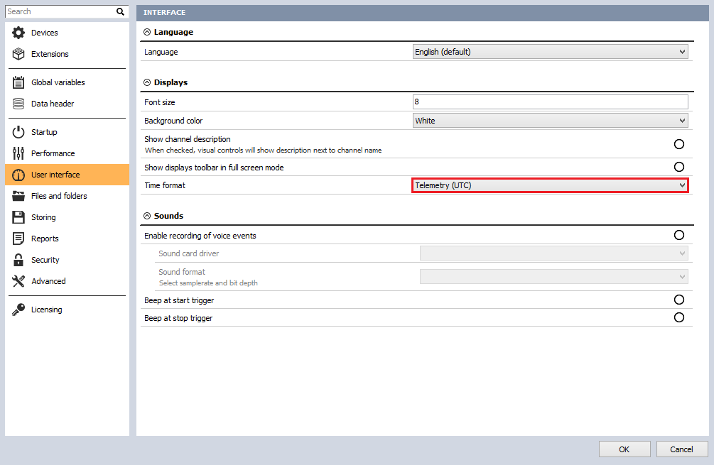
The last step in setting up the software is to go to Settings and select User Interface. Ensure that the time format is set to Telemetry (UTC).

PCM Plugin: bit sync configuration
Go to the Channel Setup screen by either clicking the Ch. Setup tab in the top toolbar or pressing F2 on your keyboard. The setup screen will appear. Next, click the PCM tab and then press the Bit Sync button.


On this screen, you configure the channel source information. Depending on your data source, the available options may vary. With the Chapter 10 input source, you can select the PCM channel source and set up the bit rate, unless it is already defined in the TMATS section of your stream. In that case, simply click the Load Settings from Channel button. This will automatically configure the data and frame sync information if it is included.
If you are using the Dewesoft Frame Sync Box, you will need to provide the software with additional information about your stream, such as bit rate, code type, polarity, and more. The Eye Diagram will display simulated graphics when working with Chapter 10 and will function as a scope of the data when working with other hardware.
If multiple PCM channel sources exist within a single system, they will run independently and must be set up separately. Each stream can be selected using the drop-down menu shown below:


Eye diagram
This display shows the incoming PCM stream in the classic “eye diagram” graph (simulated in Chapter 10 mode).


Using the Persistence selector, you can set how many plots are displayed on the screen at once. The default setting is 25, which generally provides the best visual reference. You can increase the persistence to 50 or 100, but this requires more computer memory and takes longer to update the display. For most applications, the recommended setting is 25.
Use the Pause button to temporarily freeze the eye diagram for visual analysis. Press the button again to resume display updates. The Used button allows you to view your eye pattern in a 2D graph in Measure mode.
Waveform diagram
This display shows the incoming PCM stream (simulated in Chapter 10 and iNet modes) in a conventional Y/T graph (amplitude versus time, similar to an oscilloscope display). The amplitude is shown as a percentage, and time is shown in milliseconds (ms):


You can hover the mouse over the waveform, and the display will calculate the amplitude (vertical Y-axis) and time (horizontal X-axis), displaying the values numerically at the bottom of the graph.
FFT diagram
This display shows the incoming PCM stream (simulated in Chapter 10 and iNet mode) in an FFT graph (magnitude versus frequency, i.e., spectral view), where the magnitude is shown in decibels (dB) and the frequency in Hertz (Hz, kHz, or MHz).


You can hover the mouse over the waveform, and the display will calculate the magnitude in dB (vertical Y-axis) and the frequency (horizontal X-axis), showing them numerically at the bottom of the graph.
You can also select the window type for the FFT display and adjust the zoom level from the drop-down menu.
The Rectangular window does not affect the FFT decomposition, while the other options are industry-standard algorithms used to shape the lobes of the FFT analysis. These methods improve calculation accuracy depending on the signal type.
Reference bar
At the bottom of the bit sync setup screen, there is a reference bar that displays several important parameters:


The core elements shown here are also displayed when you switch to other setup screens. These include:
Info ON/OFF indicates which stream is being monitored.
Bit rate shows the bit rate for the selected stream.
Signal strength shows the strength as a percentage for the selected stream
Bit sync shows the status of the signal lock on the selected stream.
Polarity shows the current polarity (Normal or Inverted) for the selected stream
The headers of the parameters—Bit Rate, Signal Strength, Bit Sync, and Polarity—are actually clickable buttons.
When you press any of these header buttons, the corresponding parameter becomes an available channel in the DewesoftX display screens, under the status folder of each card. This allows you to display it on the screen in a digital meter, status display, tabular display, recorder window, or any of the graphical display widgets available within the software.
PCM plugin: frame sync configuration
Go to the Ch. setup screen by either clicking the Ch. setup tab in the top toolbar or pressing F2 on your keyboard. The setup screen will appear. Next, click the PCM tab, and then press the Frame Sync button.


On this screen, you define the framing of the data within the PCM stream, including the data length, frame format identifier, and any asynchronous embedded streams that may be present. Other important settings include the frame lock criteria for the major and minor frames.
The option "Write Frame to Channel or Stream TAD file while storing" should only be used if the source is not Chapter 10. Use these checkboxes to instruct the software to automatically archive data to the hard drive in a TAD (Ulyssix Data format) file and/or a C10 (IRIG Chapter 10 format, if the system is licensed) file when storing is active.


Skip Bytes – This checkbox allows you to define a number of bytes to retain or skip if there is a section of the PCM data that should be ignored.


When you check the Skip Bytes box, two fields labeled Keep and Skip will appear automatically. Click into these fields and enter the desired number of bytes. The byte count begins with the first byte in the frame sync pattern.
Templates – Templates provide a time-saving method for storing commonly used frame configurations for frame sync. If a template is available in the selector, simply choose it and click the Load button to activate it.


To load another template, click the down arrow next to the Load button. A submenu will appear.
Next, move to the Frame Setup table to define the total number of bits in the frame sync pattern, which can range from 16 to 33 bits. In Image 34, the default value was 24, and we changed it to 32. To update this value, simply click into the field and edit the number shown in Image 34.


If you are using the IRIG Standard frame sync patterns, the hexadecimal value will be filled in automatically. To change this value, simply click the field and edit it.
Select Use Mask to set a mask value that instructs the frame sync to ignore certain bits of the sync word. If using a mask, enter a value according to the following logic rule: a logic high or '1' in any bit position will cause that bit to be ignored.
Example:
Sync word size: 32 bits
Sync pattern: FE6B2840 (Hexadecimal)
Mask value: 0000F000 (Hexadecimal)
In this example, the Frame Sync will ignore bits 12 through 15 during sync detection. Any value in the PCM stream at the location of the '2' in the FE6B2840 pattern would still result in a valid frame lock.


Now enter the number of minor frames per major frame (in image 36, the value entered is 63). Simply click the field and type your number.


Now enter the Last Word Number in the minor frame (in image 37, the value entered is 160). Simply click the field and type your number. Next, enter the number of bits per word by clicking the field and entering the correct value (in image 37, the value entered is 16). This setting depends on the Word Count defined under Hardware Setup.


If your frame definition has variable bits per word, simply click the Bits Per Word label. A new screen will then open, allowing you to set up your word size.
Note: You can copy and paste from Excel to make data entry easier.


How to configure the sub-frame sync?
To configure the Sub-Frame Sync, select one of the following options: SubFrame ID Counter (SFID), Frame Code Complement (FCC), or No Minor Frame Sync (None).

, Frame Code Complement (FCC), or No minor frame sync (None)")
Set up the SFID by entering the word location number of the SFID word within the frame. For example, if you have a 32-bit frame sync pattern with 16-bit words, and the SFID is the first word after the sync, then the start word is 3.


Then, enter the start bit in the SFID word and specify the total number of bits.
Next, select the word order (Up or Down) using the toggle button. If it shows Up, clicking it will switch the direction to Down, and vice versa. The numbers will automatically flip to match your selection. In image 40 above, we selected Up, so the numbers count upward from 0 to 63. If we select Down, the numbers flip to count downward from 63 to 0.
The Frame Format Identifier (FFI) word is used by the decom hardware to detect a unique pattern in the PCM stream and perform a format switch.
If your data stream contains one or more Frame Format Identifiers (FFIs), check this box. Then enter the integer value corresponding to the word location in the frame, followed by the word length in bits, as appropriate for your data.


When you check the FFI box, you will be prompted to enter the integer value of the Frame Format Identifier (FFI):


We entered 129 into the dialog box and then clicked OK to set this FFI value.
Next, enter the minor frame in which the FFI begins in the Start Frame field. In this example, it starts in the first minor frame, so we enter 0.
Enter the Interval, which specifies how many minor frames must pass before the FFI appears again. In this example, the interval is set to 1, meaning the FFI will appear in every minor frame. If the interval were set to 100, the FFI would appear only in every 100th minor frame.
To add another FFI, click the Add button. The same dialog box will appear, allowing you to enter the new value. Once more than one FFI exists, you can use the selector to switch between them and edit their properties.
How to configure the asynchronous embedded PCM stream?
If your PCM stream contains one or more asynchronous PCM streams, click the Add Async button to add each stream, and then define its settings.


When you add an asynchronous stream, you must define its location within the top-level PCM stream. Enter the starting word and ending word by clicking into the respective fields. If the stream is not a continuous block of words between the start and end positions, you can use Super Comm to set up an interval.


Use the ADD ASYNC button to add another asynchronous stream, or the DEL ASYNC button to delete the selected one. With these controls, you can add and manage multiple asynchronous streams.
DewesoftX can process multiple asynchronous PCM streams simultaneously. To configure each asynchronous PCM frame format, use the drop-down menu below to switch between the different streams.


Frame lock criteria
Frame Lock Criteria – the allowed transitions that the hardware requires before changing the frame status from search → check, and then from check → lock. Likewise, it defines the transitions required before changing the status from lock → check and from check → search. These values must be integers representing the number of frames, and normally low values (one or greater) are used.


Sync window (bits), also known as bit slips, defines the number of allowed bit errors in the total number of bits per minor frame.
Allowed sync error (bits) specifies the number of bit errors permitted in the frame sync pattern while still maintaining lock on the data.
Use the Data in Search Mode option if you want data to be available regardless of frame lock.
Minor Frame Lock Criteria – the allowed transitions that the hardware requires before changing the minor frame status from search → check, and then from check → lock. It also defines the transitions required before changing the status from lock → check and from check → search. These values must be integers representing the number of frames, and normally low values (one or greater) are used.
How to configure the decom?
On this screen, you configure the system to decommutate the PCM stream. This process sets up the software to extract individual parameter data from the PCM stream. The extracted data is then identified, combined, and processed, allowing the user to visualize and analyze the PCM data.


Notice the selector, which currently says "Main stream" in image 47. You can use this to select your asynchronous stream (if it has been defined in the Frame Sync Setup). The channels from that stream will then be shown on the main display. To define parameters, click the selector and choose the desired stream.


The Add/Remove buttons are used to add or remove parameters in the decom setup.
The Copy/Paste buttons use the Windows clipboard to copy selected parameters (indicated by the highlighted index number) to the clipboard. The user can then paste these parameters into other cards within the same system.
The Import button is used to import registered parameter lists from DewesoftX, allowing for easy loading of parameter setups.
Parameter table heading definitions


| Parameter | Description |
|---|---|
| Index | Is the number from 0 to n (the total number of channels plus one) of the parameter |
| On/Off | The used/unused status of the scaled output from this channel (when set to "Used", it can be displayed and recorded) |
| On/Off Raw | The used/unused status of the raw (unscaled) output from this channel (when set to "Used", it can be displayed and recorded) |
| C | Defines the color of this channel. It can be set here by clicking the color icon or on the Channel Setup screen |
| Name | Defines the name of this channel. It can be set here or on the Channel Setup screen |
| Word | Is the word number in the minor frame of this channel |
| Start frame | Is the start frame of this channel, will be a number unless the channel is set to "Normal comm" instead of subcom or supercom |
| Rate | Is the update rate of this channel from the Decom Setup |
| Size | Is the bit length of this channel |
| Values | Are a preview of this channel, scaled against the min/max values |
Parameter vonfiguration
This is one of the most important aspects of the system, as it is where you define the parameters, or "channels," that will be extracted and made available for display and recording within the software.

Press the Add button to open a new channel setup window, or modify an existing channel by pressing the Setup button at the end of each parameter row.


| Setting area | Setting | Description |
|---|---|---|
| Channel info - here you can set up the top-level properties of the selected channel. | Name | Enter a name for this channel. This is what will be displayed in the caption in measure mode. |
| Description | Optionally enter additional info about this channel. | |
| Units | Enter the engineering units for this channel (V, A, degrees, PSI, etc.). | |
| Colour | Click this windows widget to set the color for this channel. | |
| Delay | Enter the number of milliseconds that this channel is delayed by. | |
| Min value | Set the display scale for this channel: low side (This is for Auto Widget setting along with Overload indicators). | |
| Max value | Set the display scale for this channel: high side (This is for Auto Widget setting along with Overload indicators |
| Setting area | Setting | Description |
|---|---|---|
| Decoding and Scaling - here you set up how this channel is interpreted by the software | Date Type | This is how the data word extracted from the PCM stream is represented in memory. When Two's Comp or One's Comp is selected, the data will be represented as positive and negative values. These values will be sign-extended when extracted from the PCM stream. The Binary selection will treat data as positive binary values with no sign extension. |


Scaling values (A0, A1, A2, A3, A4, A5) – You can enter the scaling values according to the formula shown below the fields:
A0 + A1·x + A2·x² + A3·x³ ...
Enter as many scaling factor values as needed for this channel, and leave the remaining fields set to their default zero values.
| Setting area | Setting | Description |
|---|---|---|
| PCM Frame Location - you can set the commutation type and bit locations for this channel. | Commutation Type | Select from Normal, SuperComm, or SubComm for parameter type. |
| Interval | Used for your SuperComm or SubComm words. For SuperComm words this is the word interval in between the samples. For SubComm this is the minor frame interval in between samples. | |
| Bit mapping table | Here you define:Start frame - Is the minor frame number the parameter data startsStart word - Is the word number in the minor frame the parameter data startsStart bit - Is the start bit in the word where the parameter data startsLength - (in bits) of the number of bits in the parameter data | |
| Bit Concatenation | Where you need to combine bits from different parts of the frame to make one parameter. Ex imbedded Time. | |
| Use the [+] and [-] buttons to add indices to the bit mapping table. Then you can click within each value in the newly created row or You can also select any index number. | ||
| Use the Trigger index if there is more than one item in a bit mapping table; the user can select what is a trigger index for writing a sample to a Dewesoft X channel. | ||
| Select ET (Embedded Time) to set-up embedded time in the PCM stream as a decom word. The user can define each BCD time digit to a specific nibble in the PCM word. | ||
| Select Synchronous Channel to create a Dewesoft X channel as a synchronous channel, constant rate. | ||
| Select Array channel with channels that have more than one sample (n-m samples, in most cases it is a vector) and is used for special calculations; for example, Missed Distance Calculations | ||
| Values Preview | A very useful tool to look at the values preview at the bottom of the dialog to see the effect of your scaling against the real data. It also gives an overall view of the parameter as you concatenate bits together to build a parameter.Image 55: Value preview | |
| Use raw and scaled values, these checkboxes serve exactly the same function as the Used/Unused buttons for the raw and scaled outputs from this channel, back on the Decom setup screen. You can also set them here using these checkboxes. |
How to import a parameter list?
You may import a list of parameters that have already been defined in a TXT file, TMATs file, or CSV file. To do this, click the Import button as shown on the Decom setup screen:

You will be presented with the Open dialog box, where you can navigate your computer to locate the file you want to load.
What does the frame preview screen show?
The frame preview screen provides a clear view of the raw live frame dump of the major frame data in hexadecimal format. The first minor frame, along with its time stamp, appears at the top. Channel color labels indicate the parameter locations within the major frame.

By clicking on a word in the major frame, a window will appear displaying detailed information about that specific word.


If that word is not defined as a parameter, select Add New Channel. This will automatically open the decom channel setup screen with the correct frame location information pre-filled.
IRIG 106 CHAPTER 10 - digital recording standard
A large number of unique and proprietary data structures have been developed for specific data recording applications, each requiring its own decoding software. The tasks of writing custom decoding software, verifying its accuracy, and decoding the data tapes are extremely time-consuming and costly.
In the late 1990s, test ranges began implementing non-tape-based, high-data-rate recorders, the most common of which were solid-state memory devices. As high-data-rate digital recorders became more widely used and solid-state technology continued to advance, the Telemetry Group (TG) recognized the need for a computer-compatible digital data acquisition and recording standard and formed an ad hoc committee to address it.
There remains a clear need for a digital data acquisition and recording standard that supports a wide range of requirements, including:
Data download and interface
One or more multiplexed data streams
One or more single data streams
Data format definitions
Recorder control
Media declassification
Data interoperability
Specifically, this digital recording standard shall be compatible with the multiplexing of both synchronous and asynchronous digital inputs, such as Pulse Code Modulation (PCM), MIL-STD-1553 data bus, time, analog, video, ARINC 429, discrete signals, and RS-232/422 communication data.
This standard will also enable the use of a common set of playback and data reduction software, allowing full utilization of emerging random-access recording media.
This standard does not prescribe a specific hardware architecture, such as the coupling of data acquisition, multiplexing, and media storage. The required interface levels are defined within this standard.


DewesoftX IRIG 106 chapter 10 plugin
What is the Dewesoft X IRIG 106 Chapter 10 plugin?
The Dewesoft Chapter 10 plugin is a specialized tool designed to read either a previously recorded data file or a real-time Ethernet stream containing Chapter 10–formatted data.
What does it do?
The Dewesoft Chapter 10 plugin receives the incoming Chapter 10 data stream either from a playback file on the hard drive or from a real-time Ethernet stream. It then extracts the embedded time information from the Chapter 10 file to synchronize the Dewesoft master clock. After that, the plugin processes each data channel included in the stream.
For analog, video, and discrete data, the Chapter 10 plugin routes the information into the appropriate data channels for processing and display. More complex data types, such as PCM and ARINC 429/MIL-STD-1553, are handed off to their respective Dewesoft plugins for further processing, ultimately producing the individual measurement channels.
How to start?
To get started, the following files are required:
Dewesoft X Data Acquisition Software. You can download the latest version from https://download.dewesoft.com.
IRIG 106 Chapter 10 plugin for Dewesoft X Software
PCM Telemetry Plugin for Dewesoft X Software
Telemetry Camera Plugin for Dewesoft X Software
All the above files can be downloaded from Dewesoft Download Center.
Copy all plugin files into the Dewesoft/Addons folder. Then, run DewesoftX, go to Settings → Devices, and add the Chapter 10 extension.


In the Chapter 10 Hardware settings, there are two modes that the plugin can run in:
Recorder Mode: In this mode, the plugin acquires data from various sources in the software in real time. DewesoftX can then either record this data to the computer’s hard drive in a .CH10 file format, or transmit it in real time over Ethernet using a Chapter 10–defined packet structure for other devices to receive.
Reproducer Mode: In this mode, the plugin reads a Chapter 10–formatted data stream and processes it within DewesoftX. The Input Type: Chapter 10 file option allows you to read a .CH10 file directly from the computer’s hard drive. The other option, Input Type: Ethernet, allows you to receive a Chapter 10 Ethernet packet from another device in real time for processing.


Then go to Channel Setup and open the Chapter 10 tab. The following screen will appear:


As shown in image 62, the file was not found. The next steps are:
A) Select the Chapter 10 (.ch10) file or multiple files (with the same setup).
Use the + button to add files and the - button to remove unwanted files. If using multi-file playback, the Up button can be used to reorder the files.
B) Choose the start and stop positions in the file.
This allows you to play back only a selected section of the recording. The "..." button lets you set exact times for playback. You can also replay the file at a faster or slower rate. Continuous Loop Mode repeats the Chapter 10 file for playback testing, while Fast Playback ignores the recorded speed and processes the file as quickly as the computer allows, saving the results to a DXD file once the Store button is pressed.
C) Add or remove channels, import channels, and auto-scan.
The Add and Remove options let you manually define channels in your Chapter 10 file. The Import button allows you to load a TMATS file for setup. The Auto-Scan button scans the Chapter 10 file for built-in TMATS data and configures the Chapter 10 plugin automatically.
D) Enable the desired channels, rename them, or view details in the setup.

In this way, you can preview and enable different types of channels, such as AI, Time, UART, Discrete, Video, and more. The following chapters will explain how to do this.
Analog and discrete channels
To enable analog or discrete data packets, set the desired channels to Used:


To display the data, go to Measure → Design mode. We will present the signals using two different controls: Recorder for analog signals and Tabular Values Display for discrete signals. Next, add each control to the desired location and assign the appropriate channels to it.


The discrete value channel is displayed in Raw Scaling (a). In the bottom left (b), the Binary format was selected from the left-hand menu (c), while in the second display (d), the Hex format was selected..
Video stream
To enable the video stream, add Telemetry Video under Add Device → Camera.


After that, go back to Channel Setup, and you will see that the Video tab has already been generated with PCM telemetry cameras inside.


We can preview the video stream under Setup. To present a video stream in Measure mode, go to Add Widget, select the Video visual control, and assign the Camera 0 channel to it.
PCM stream
First, enable PCM channels:


Now we can display PCM channel values in the Measure tab by navigating to Design → Add Tabular Display Data, then selecting the PCM Data channel on the right. Also, enable Raw scaling and Hex format in the left section.

Decoding PCM Stream


Click OK, go to Ch. Setup, click PCM icon, select PCM data as Input Channel (it is available if tetelemePCM channel is enabled in Ch.10 setup) and click Load Settings from Channel button to load setting from Chapter 10 file (TMATS settings).


Now you can see the Frame Sync window:


To add a channel, go to Frame Preview and click on the PCM Frame -> Add New Channel:

A new window will open, allowing you to set the parameters of the new channel:


Measure
We can view all enabled channels in the Measure tab using the appropriate visual controls, which can be selected and arranged in Design mode. To display the desired channels, simply click on their names in the right panel.


Additionally, we can add live mathematics or apply them in Analysis mode to all channels under Ch. Setup → Math.
Finally, the stored channels can be exported in various formats supported by DewesoftX.
Page 1 of 17